Cumulus Basics Part V - BGP unnumbered
In this post, we’ll look at BGP unnumbered on Cumulus Linux.
Introduction
The last post introduced basic BGP bringup on a Cumulus box with OSPF as the IGP. Let’s now move towards a BGP unnumbered design and understand how that works.
Topology
We will use the same network topology as before:
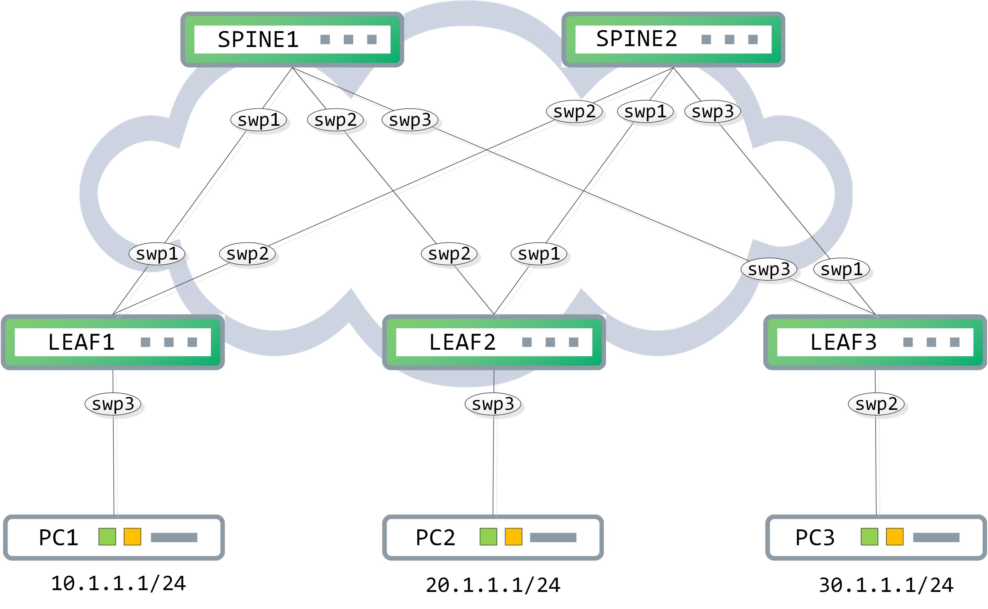
The idea behind BGP unnumbered is to use the IPv6 link local addressing on hop by hop basis. When you’re building a L3 fabric, what is the goal of the underlay? Outside of any multicast replication that may be required, the main goal (from a unicast perspective) is to provide connectivity from one tunnel end point to another. Typically, you would use something like OSPF or IS-IS to advertise the loopbacks of the tunnel endpoints and thus, provide connectivity from one loopback to another.
Now, with that premise in mind, let’s break it down some more. What is really done on a per hop basis? Each node is simply doing a L3 lookup, resolving the next hop’s address, rewriting the L2 header and forwarding it on towards the next hop. This entire process can be lifted away from an IGP and done via BGP itself, by utilizing link local IPv6 addressing and RFC 5549, which allows you to advertise an IPv4 NLRI with an IPv6 next hop. And how do you resolve the IPv6 next hop? Using the IPv6 neighbor discovery process.
Let’s start putting some of these pieces together now. First, we enable IPv6 ND on the point to point links and disable RA suppression (which appears to be enabled by default).
cumulus@LEAF1:~$ net add interface swp1-2 ipv6 nd ra-interval 10
cumulus@LEAF1:~$ net del interface swp1-2 ipv6 nd suppress-ra
cumulus@LEAF1:~$ net commit
This adds the following to ‘/etc/frr/frr.conf’ file:
cumulus@LEAF1:~$ sudo cat /etc/frr/frr.conf
[sudo] password for cumulus:
Sorry, try again.
[sudo] password for cumulus:
frr version 4.0+cl3u10
frr defaults datacenter
hostname LEAF1
username cumulus nopassword
!
service integrated-vtysh-config
!
log syslog informational
!
interface swp1
 ipv6 nd ra-interval 10
 no ipv6 nd suppress-ra
!
interface swp2
 ipv6 nd ra-interval 10
 no ipv6 nd suppress-ra
!
line vty
!
From ‘net show interface <>’ you can confirm the link local IPv6 address, the mac address associated with this interface, Router Advertisement (abbreviated to ‘RA’ going forward) interval and so on:
cumulus@LEAF1:~$ net show interface swp1
    Name  MAC                Speed  MTU   Mode
--  ----  -----------------  -----  ----  -------------
UP  swp1  50:00:00:03:00:01  1G     1500  NotConfigured

cl-netstat counters
-------------------
RX_OK  RX_ERR  RX_DRP  RX_OVR  TX_OK  TX_ERR  TX_DRP  TX_OVR
-----  ------  ------  ------  -----  ------  ------  ------
54708       0      18       0  57169       0       0       0

Routing
-------
  Interface swp1 is up, line protocol is up
  Link ups:       1    last: 2019/04/29 03:51:10.27
  Link downs:     1    last: 2019/04/29 03:01:38.14
  PTM status: disabled
  vrf: default
  index 3 metric 0 mtu 1500 speed 1000
  flags: <UP,BROADCAST,RUNNING,MULTICAST>
  Type: Ethernet
  HWaddr: 50:00:00:03:00:01
  inet6 fe80::5200:ff:fe03:1/64
  Interface Type Other
  ND advertised reachable time is 0 milliseconds
  ND advertised retransmit interval is 0 milliseconds
  ND router advertisements sent: 51 rcvd: 2
  ND router advertisements are sent every 10 seconds
  ND router advertisements lifetime tracks ra-interval
  ND router advertisement default router preference is medium
  Hosts use stateless autoconfig for addresses.
  Neighbor address(s):
  inet6 fe80::5200:ff:fe01:1/128
Let’s mimic the configuration on SPINE1 as well now.
cumulus@SPINE1:~$ net add interface swp1 ipv6 nd ra-interval 10
cumulus@SPINE1:~$ net del interface swp1 ipv6 nd suppress-ra
cumulus@SPINE1:~$ net commit
Again, look at ‘net show interface swp1’ to confirm the mac address and the IPv6 link local address:
cumulus@SPINE1:~$ net show interface swp1
    Name  MAC                Speed  MTU   Mode
--  ----  -----------------  -----  ----  -------------
UP  swp1  50:00:00:01:00:01  1G     1500  NotConfigured

cl-netstat counters
-------------------
RX_OK  RX_ERR  RX_DRP  RX_OVR  TX_OK  TX_ERR  TX_DRP  TX_OVR
-----  ------  ------  ------  -----  ------  ------  ------
57216       0      44       0  54847       0       0       0

LLDP Details
------------
LocalPort  RemotePort(RemoteHost)
---------  ----------------------
swp1       swp1(LEAF1)

Routing
-------
  Interface swp1 is up, line protocol is up
  Link ups:       1    last: 2019/04/29 04:01:52.99
  Link downs:     1    last: 2019/04/29 03:04:24.45
  PTM status: disabled
  vrf: default
  index 3 metric 0 mtu 1500 speed 1000
  flags: <UP,BROADCAST,RUNNING,MULTICAST>
  Type: Ethernet
  HWaddr: 50:00:00:01:00:01
  inet6 fe80::5200:ff:fe01:1/64
  Interface Type Other
  ND advertised reachable time is 0 milliseconds
  ND advertised retransmit interval is 0 milliseconds
  ND router advertisements sent: 81 rcvd: 80
  ND router advertisements are sent every 10 seconds
  ND router advertisements lifetime tracks ra-interval
  ND router advertisement default router preference is medium
  Hosts use stateless autoconfig for addresses.
  Neighbor address(s):
  inet6 fe80::5200:ff:fe03:1/128
Take a look at the neighbor discovery process between LEAF1 and SPINE1 now.
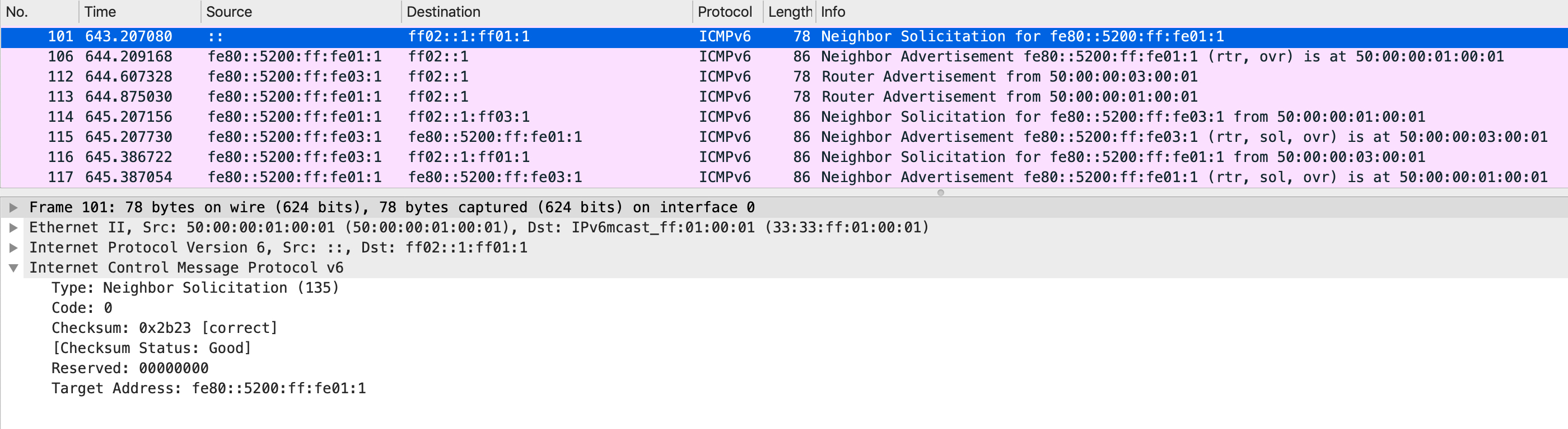
First, SPINE1 sends out a neighbor solicitation (abbreviated to ‘NS’ going forward) message with a target address of itself. This is sent to a well known multicast address:
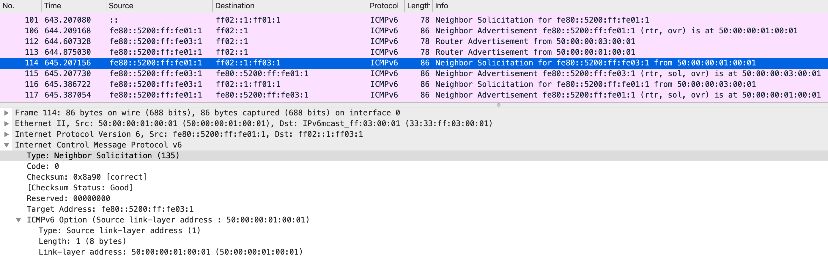
After a back and forth RA, another NS is sent by SPINE1 but this time, with a target address of ‘fe80::5200:ff:fe03:1’, which corresponds to the link local IPv6 address assigned to swp1 of LEAF1. Notice how the ICMPv6 option also specifies the link-layer address, which corresponds to SPINE1, swp1’s mac address.
LEAF1 responds to this with a Neighbor Advertisement (abbreviated to NA going forward) message.
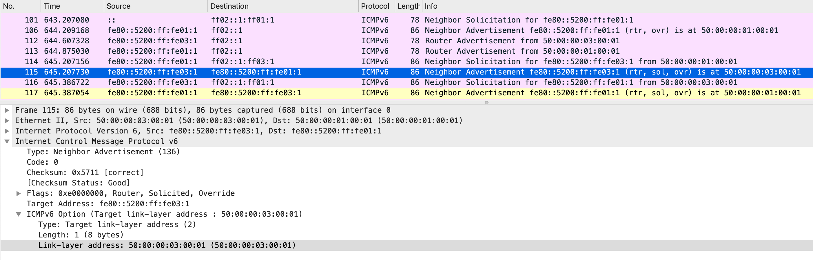
Notice that the link-layer address in the NA sent by LEAF1 is the mac address of its port, swp1. SPINE1 can now use this information to build its IP neighbor table. The same process happens the other way around, with LEAF1 sending a NS and SPINE1 responding back with a NA. At the end of this, both should have their IP neighbor tables correctly populated.
You can confirm this using:
cumulus@LEAF1:~$ ip -6 neighbor show
fe80::5200:ff:fe01:1 dev swp1 lladdr 50:00:00:01:00:01 router REACHABLE

cumulus@SPINE1:~$ ip -6 neighbor show
fe80::5200:ff:fe03:1 dev swp1 lladdr 50:00:00:03:00:01 router REACHABLE
Let’s bring up BGP over this link now. The configuration needs to be modified a little bit since these links do not have any IPv4 address anymore (apart from their default link local IPv4 addresses). Instead of specifying an IP address in the BGP neighbor statement, Cumulus allows you to specify the port number.
// LEAF1 configuration

cumulus@LEAF1:~$ net add bgp autonomous-system 1
cumulus@LEAF1:~$ net add bgp router-id 1.1.1.1
cumulus@LEAF1:~$ net add bgp neighbor swp1 remote-as internal

// SPINE1 configuration

cumulus@LEAF1:~$ net add bgp autonomous-system 1
cumulus@LEAF1:~$ net add bgp router-id 11.11.11.11
cumulus@LEAF1:~$ net add bgp neighbor swp1 remote-as internal
A packet capture shows us the bringup sequence for BGP between these two boxes:
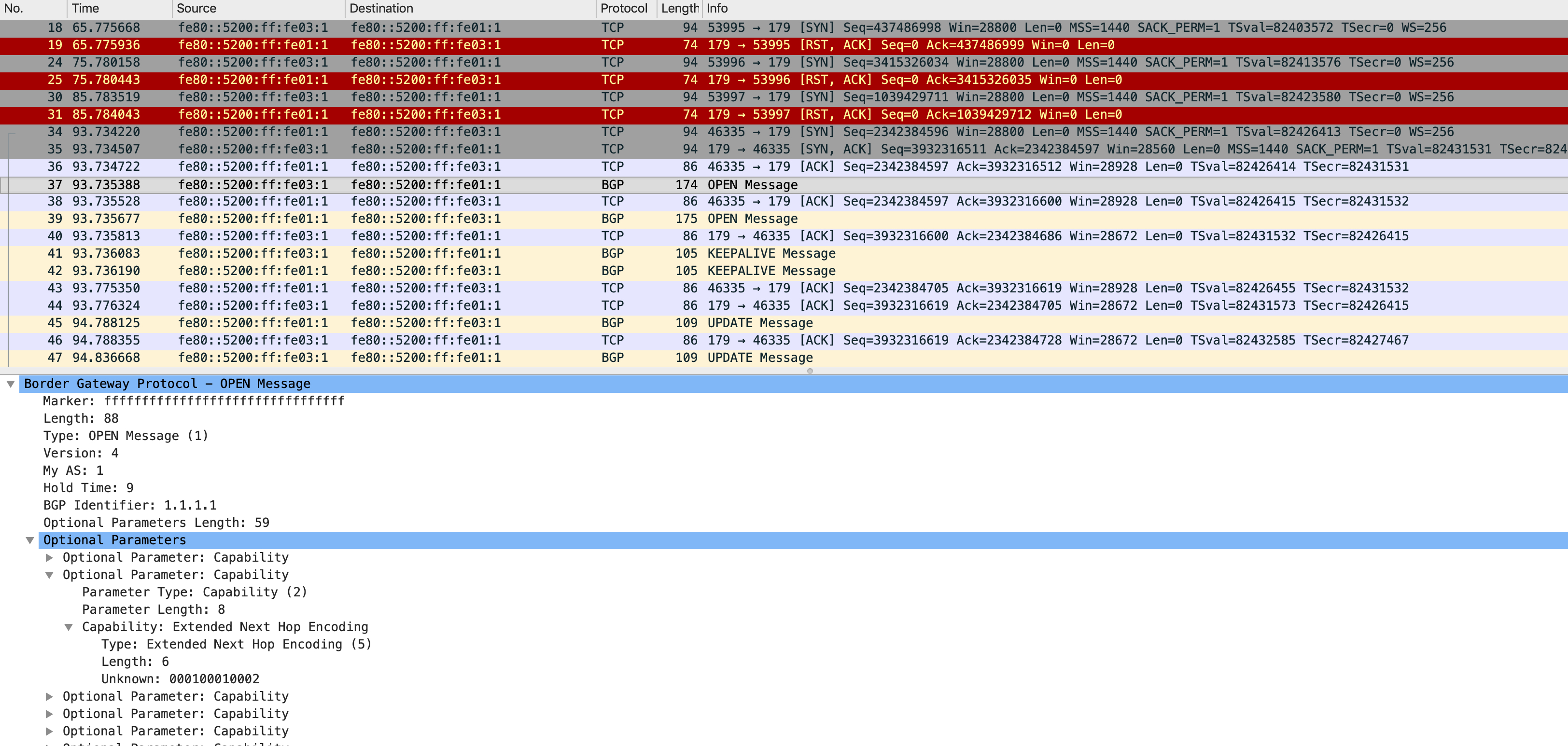
Let’s break this down quickly - initially we see several TCP resets. Why is that? Because BGP port is not open yet on SPINE1 (it was not configured at that point in time), hence any TCP SYN coming for a destination port of 179 (BGP) would be rejected by SPINE1. Once the configuration is complete on both sides, we see the 3-way TCP handshake complete and the OPEN messages being sent.
Among other capabilities exchanged in the OPEN message, an important one is highlighted in the capture - the extended next hop encoding. This allows for an IPv4 NLRI to have an IPv6 next hop. You need to make sure this capability is exchanged. To force this, you can use this ‘net add bgp neighbor capability extended-nexthop’ command on a Cumulus box.
Using a similar approach, we can complete our BGP peerings for this entire infrastructure. Remember to make each LEAF switch a route reflector client of the SPINE switches (otherwise an update from a LEAF switch will not be sent to the other LEAF switches by the SPINE because of iBGP peering rules). At the end of this, each SPINE should see three peerings - one to each of the LEAF switches:
//SPINE1

cumulus@SPINE1:~$ net show bgp ipv4 unicast summary
BGP router identifier 11.11.11.11, local AS number 1 vrf-id 0
BGP table version 0
RIB entries 0, using 0 bytes of memory
Peers 3, using 58 KiB of memory

Neighbor        V         AS MsgRcvd MsgSent   TblVer  InQ OutQ  Up/Down State/PfxRcd
LEAF1(swp1)     4          1     374     376        0    0    0 00:04:19            0
LEAF2(swp2)     4          1      31      31        0    0    0 00:01:26            0
LEAF3(swp3)     4          1       6       6        0    0    0 00:00:11            0

Total number of neighbors 3

// SPINE2

cumulus@SPINE2:~$ net show bgp ipv4 unicast summary
BGP router identifier 22.22.22.22, local AS number 1 vrf-id 0
BGP table version 0
RIB entries 0, using 0 bytes of memory
Peers 3, using 58 KiB of memory

Neighbor        V         AS MsgRcvd MsgSent   TblVer  InQ OutQ  Up/Down State/PfxRcd
LEAF2(swp1)     4          1      34      34        0    0    0 00:01:33            0
LEAF1(swp2)     4          1     125     127        0    0    0 00:04:52            0
LEAF3(swp3)     4          1       9       9        0    0    0 00:00:18            0

Total number of neighbors 3
Each SPINE has three BGP neighbors, as expected. We have not advertised the host subnets yet so let’s do that and take a packet capture to analyze how this is advertised.
cumulus@LEAF1:~$ net add bgp network 10.1.1.0/24
cumulus@LEAF1:~$ net commit
Take a look at the following capture taken on LEAF2 as it receives a BGP update from SPINE1:
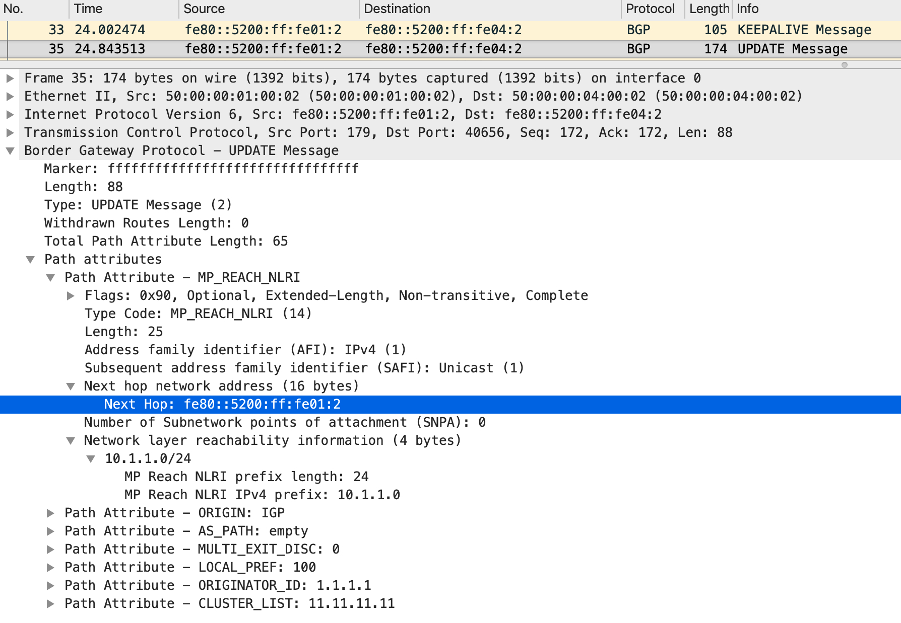
The NLRI describes an IPv4 subnet but the next hop is an IPv6 address. How cool is that? Look at the RIB/FIB on LEAF2 to confirm how this is installed:
cumulus@LEAF2:~$ net show route 10.1.1.1
RIB entry for 10.1.1.1
======================
Routing entry for 10.1.1.0/24
  Known via "bgp", distance 200, metric 0, best
  Last update 00:12:21 ago
  * fe80::5200:ff:fe01:2, via swp2
  * fe80::5200:ff:fe02:1, via swp1


FIB entry for 10.1.1.1
======================
10.1.1.0/24  proto bgp  metric 20
        nexthop via 169.254.0.1  dev swp2 weight 1 onlink
        nexthop via 169.254.0.1  dev swp1 weight 1 onlink
The RIB installs the prefix against the link local IPv6 address while the FIB installs them against the link local IPv4 address.
After advertising all host subnets, LEAF1s RIB looks like this:
cumulus@LEAF1:~$ net show route ipv4
Codes: K - kernel route, C - connected, S - static, R - RIP,
       O - OSPF, I - IS-IS, B - BGP, E - EIGRP, N - NHRP,
       T - Table, v - VNC, V - VNC-Direct, A - Babel, D - SHARP,
       F - PBR,
       > - selected route, * - FIB route

C>* 1.1.1.1/32 is directly connected, lo, 16:51:39
C>* 10.1.1.0/24 is directly connected, swp3, 16:28:27
B>* 20.1.1.0/24 [200/0] via fe80::5200:ff:fe01:1, swp1, 00:00:24
  *                     via fe80::5200:ff:fe02:2, swp2, 00:00:24
B>* 30.1.1.0/24 [200/0] via fe80::5200:ff:fe01:1, swp1, 00:00:14
  *                     via fe80::5200:ff:fe02:2, swp2, 00:00:14
PC1 should be able to ping PC2 and PC3 now:
PC1> ping 20.1.1.1

84 bytes from 20.1.1.1 icmp_seq=1 ttl=61 time=2.743 ms
84 bytes from 20.1.1.1 icmp_seq=2 ttl=61 time=1.295 ms
84 bytes from 20.1.1.1 icmp_seq=3 ttl=61 time=1.648 ms
84 bytes from 20.1.1.1 icmp_seq=4 ttl=61 time=1.637 ms
84 bytes from 20.1.1.1 icmp_seq=5 ttl=61 time=1.543 ms

PC1> ping 30.1.1.1

84 bytes from 30.1.1.1 icmp_seq=1 ttl=61 time=2.585 ms
84 bytes from 30.1.1.1 icmp_seq=2 ttl=61 time=1.402 ms
84 bytes from 30.1.1.1 icmp_seq=3 ttl=61 time=1.528 ms
84 bytes from 30.1.1.1 icmp_seq=4 ttl=61 time=1.975 ms
84 bytes from 30.1.1.1 icmp_seq=5 ttl=61 time=1.638 ms
And there it is. A thing of beauty!