Cisco SDA and Security Part I - macro segmentation in SDA
In this post, we will look at macro segmentation in Cisco’s SD-Access.
Introudction and topology
Two big things standout with SD-Access - the segmentation story and native wireless integration. This post (and the next) is going to look at segmentation and how that is achieved within the SD-Access solution.
What is segmentation? In simple terms, you’re creating boundaries between systems (or groups of systems). Using certain constructs, you control whether system A can talk to system B. This is a fairly common requirement in today’s enterprise networks - you want to be able to separate out departments and control who can talk to whom. The constructs that we use in SD-Access have existed far before this solution was brought to life - VRFs (or, in SD-Access terms, Virtual Networks commonly abbreviated to VNs) and SGTs (Scalable Group Tags or as it was previously know, Security Group Tags).
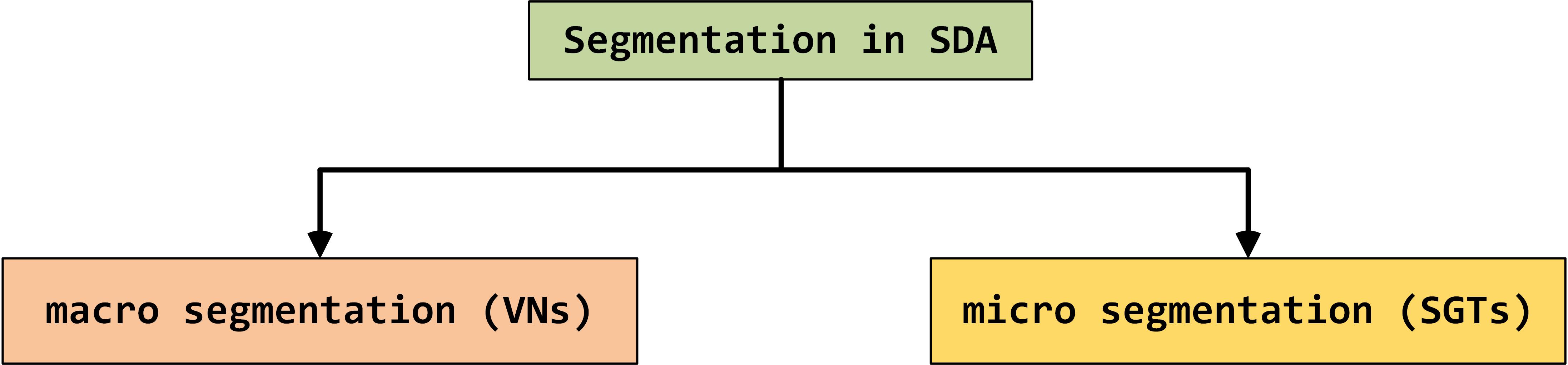
In SD-Access, VNs are a form of macro-segmentation and SGTs are a form of micro-segmentation. The general idea is a create a major boundary between groups using VNs and then further control communication between different endpoints in the same group (VN) using SGTs. Hence, the terms ‘macro’ and ‘micro’.
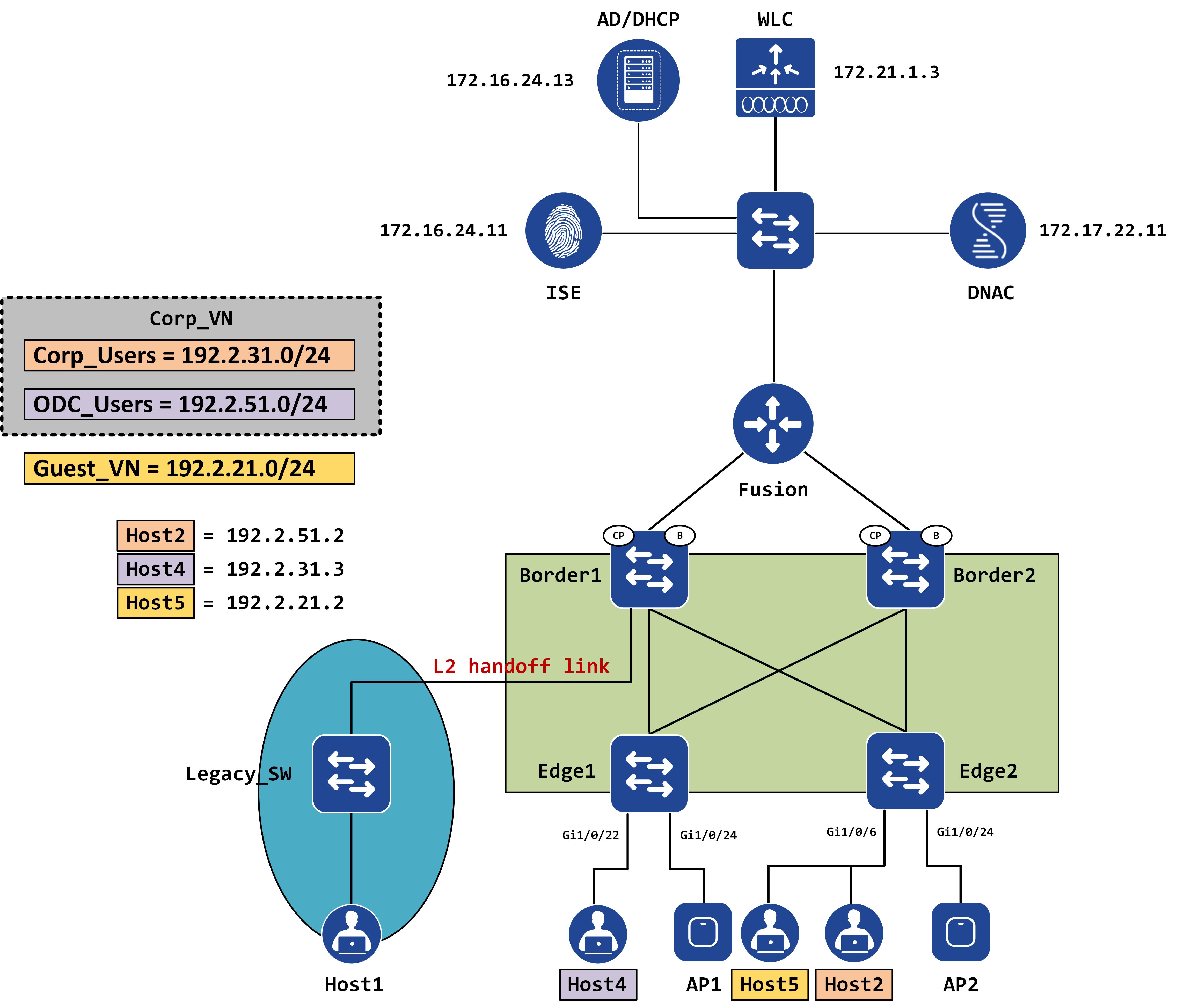
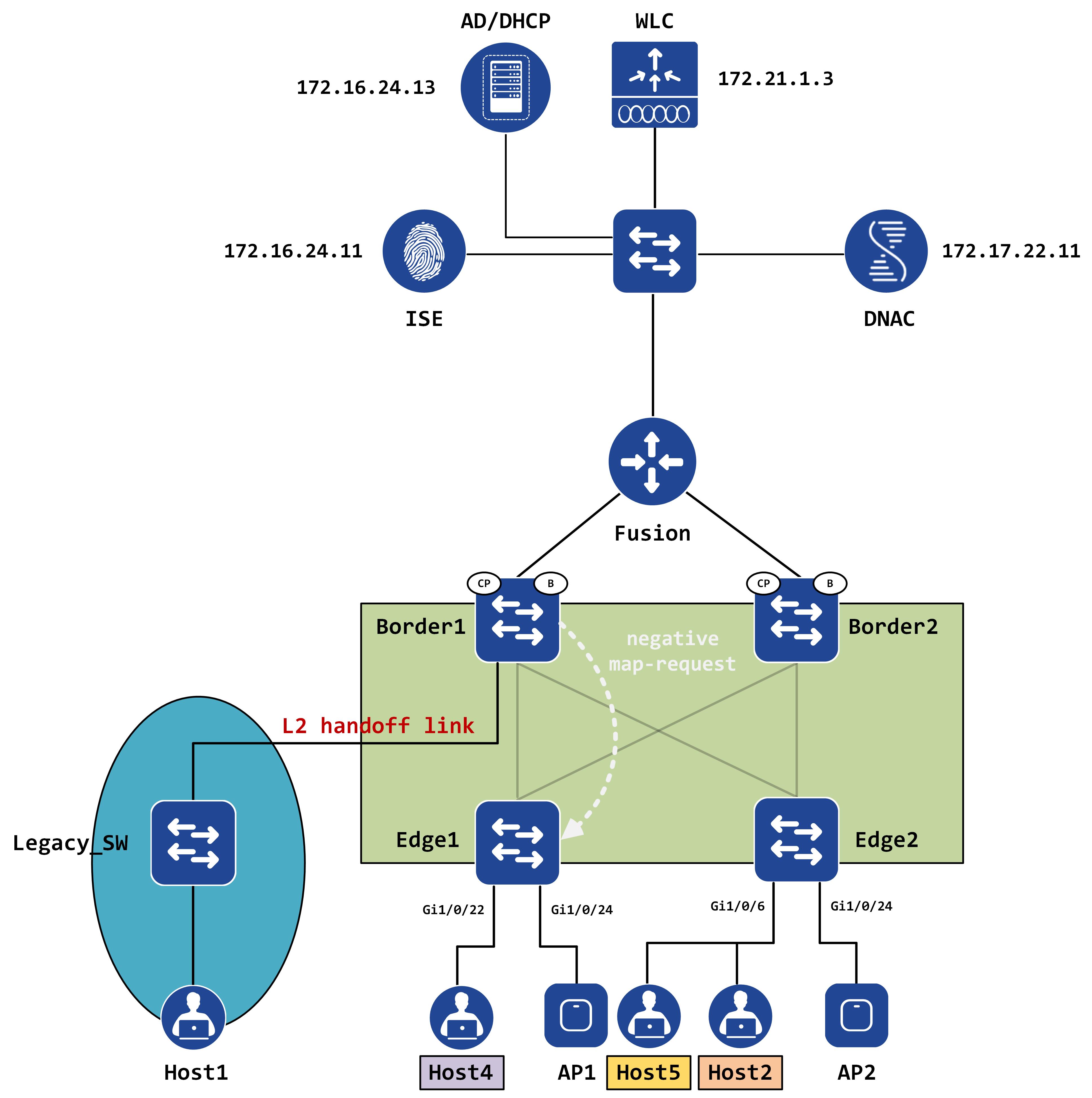
This post will cover macro segmentation while the subsequent posts will tackle micro segmentation. We’re going to continue using the same topology as some of the previous posts. Some minor differences - an AD has been added into the mix and now Host4 sits behind Edge1 (instead of Host1). Additionally, Host5 is connected to Edge2 via the same port as Host2 - gig1/0/6. Think of this as VDI environment - we’re spinning up multiple VMs, all of which physically connect to the same port on the Edge. All these VMs must also be authenticated and authorized before accessing the network.
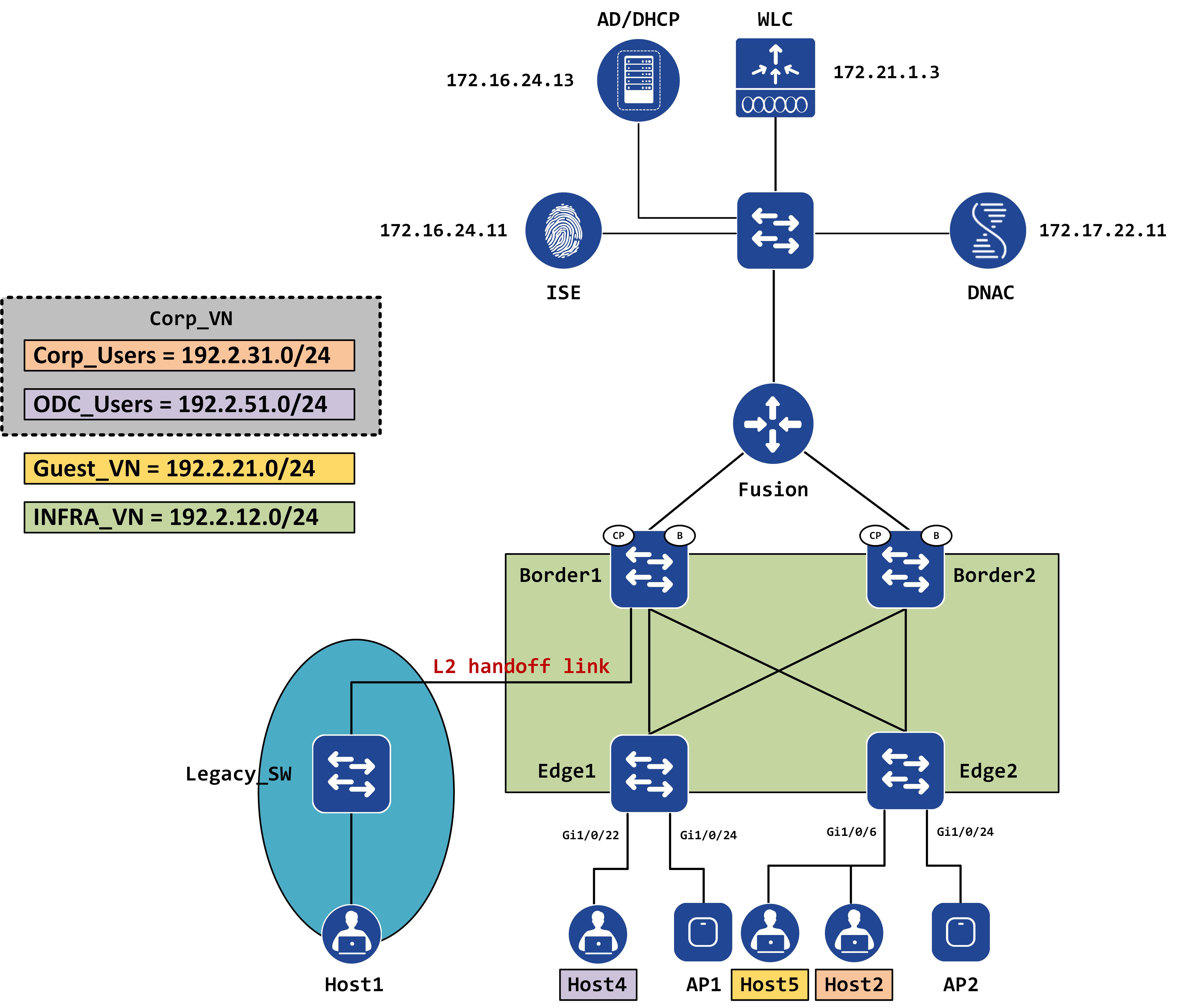
Each of the hosts have been marked with the expected VN they should belong to:
- Host5 should be a part of Guest_VN
- Host4 should be a part of ODC_Users (which belongs to Corp_VN)
- Host2 should be a part of Corp_Users (which also belongs to Corp_VN)
By the end of this, we should understand a few major things:
- How VNs are created
- How VNs provide a form of segmentation
- Why SDA requires a ‘Fusion’ device
Virtual Networks in SD-Access
So, as I stated earlier, Virtual Networks (VNs) are nothing but VRFs. Let’s quickly revisit how to create a VN. In your DNAC GUI, traverse to the “Policy” page and click on “Virtual Network”. You should get a page that lists all your VNs (including the pre-existing VNs that are created by default).
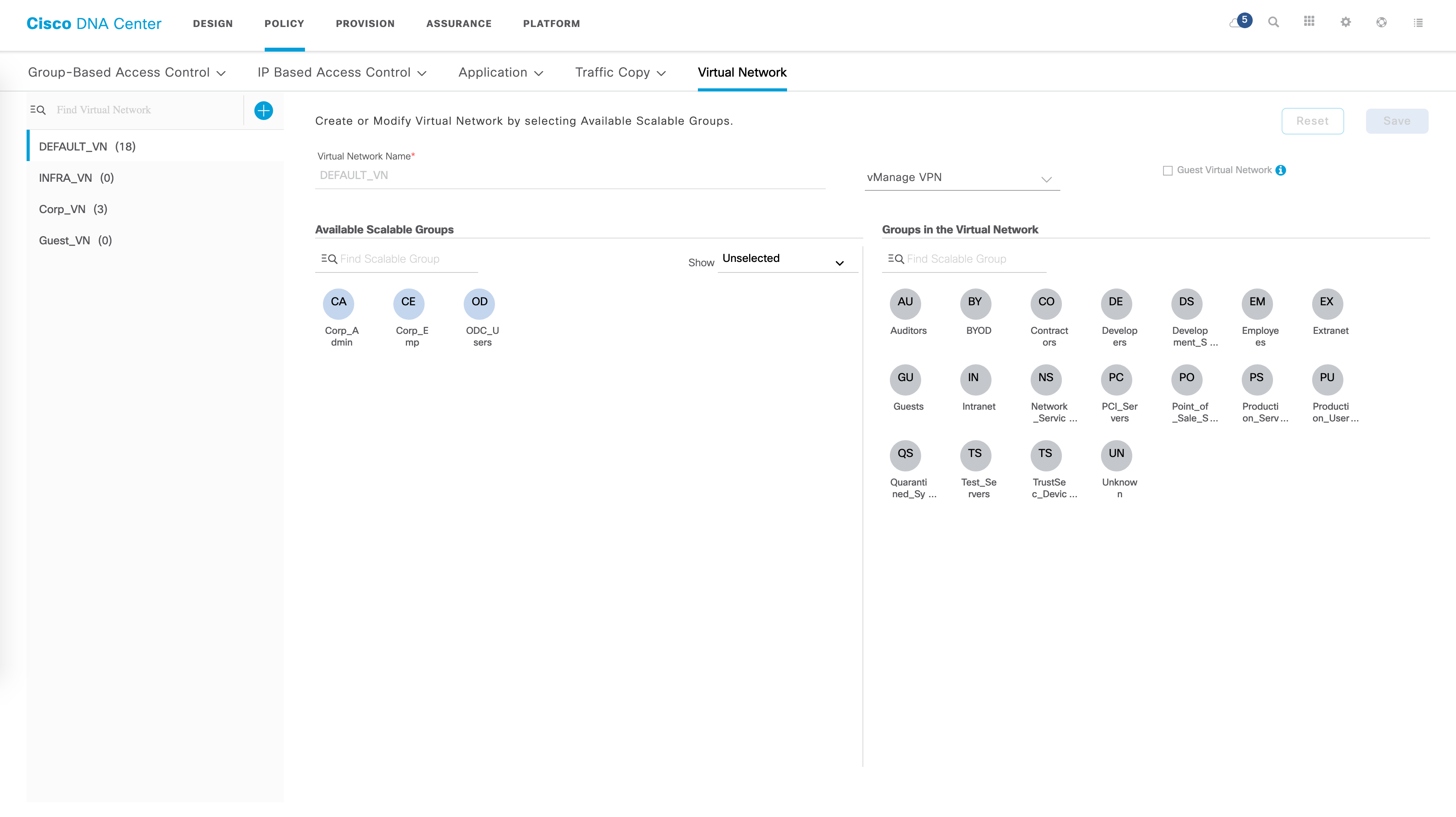
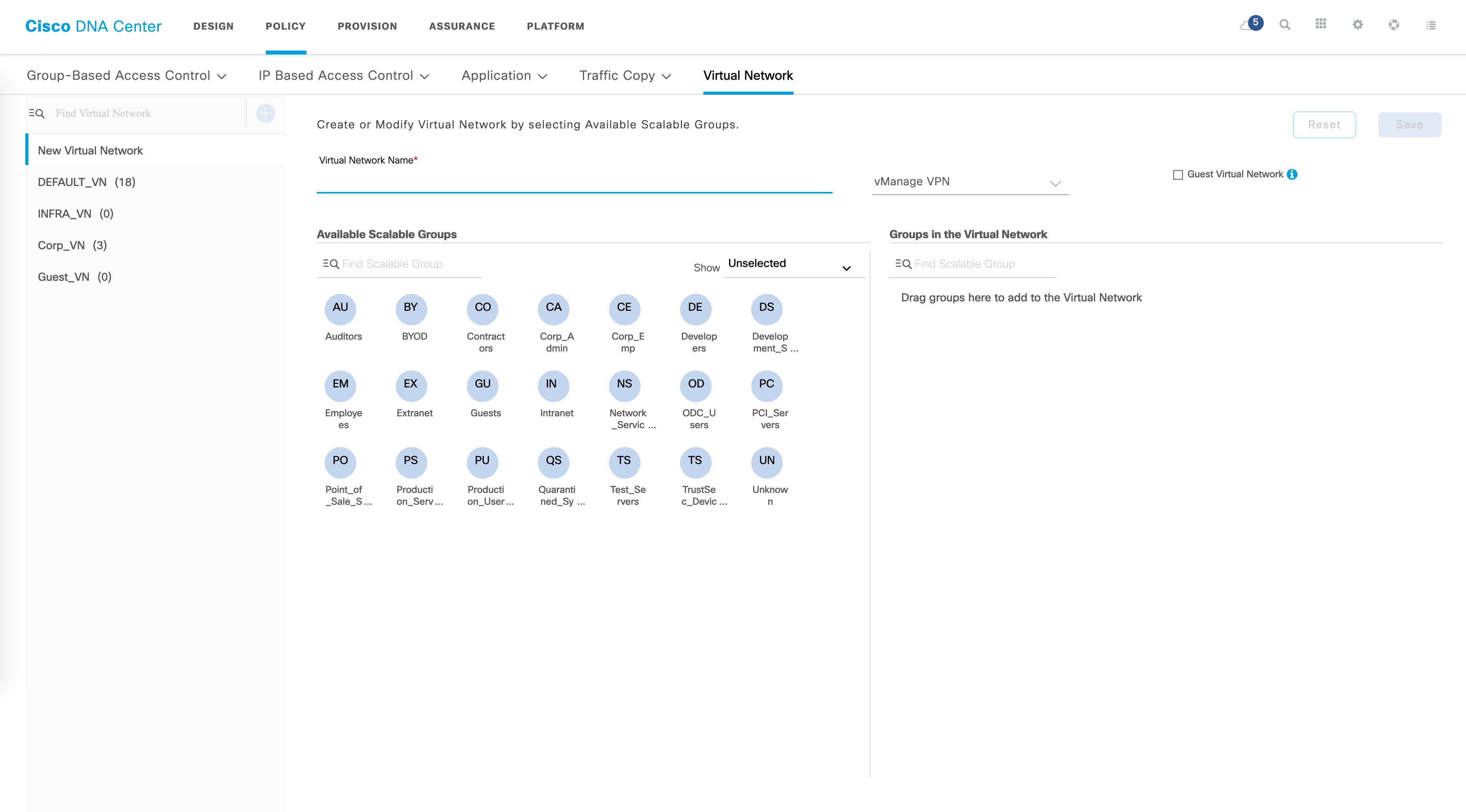
The blue “plus” sign allows you to create a new VN. Some basic parameters are needed here such as the VN name. You can also drag and drop existing SGTs to this new VN.
Once you’ve created your VN, you can go to the"Provision" page and from here click on “Fabric”, then your fabric name and eventually your site name. Your fabric should now be visible to you:
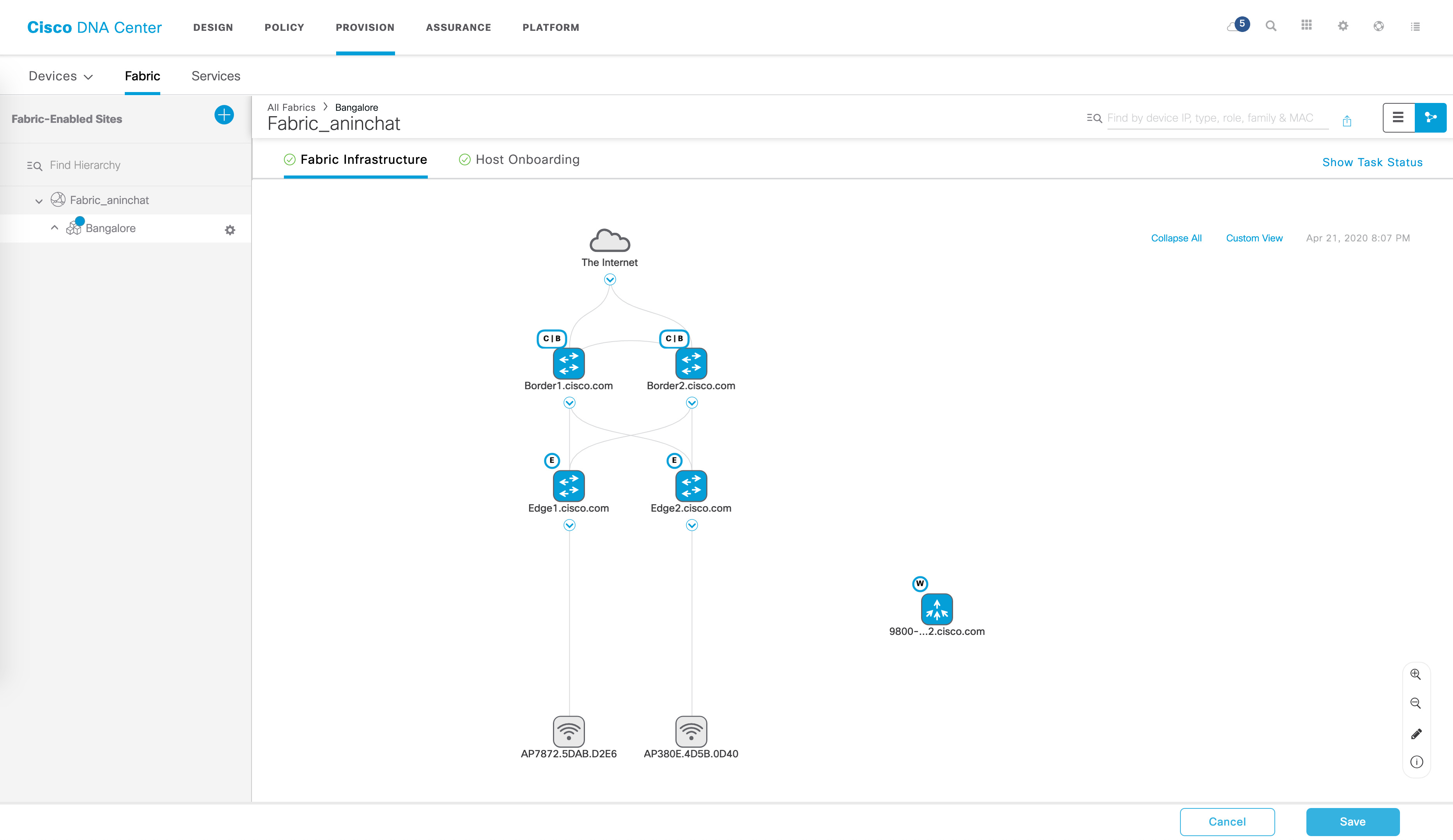
From here, go to “Host Onboarding”.
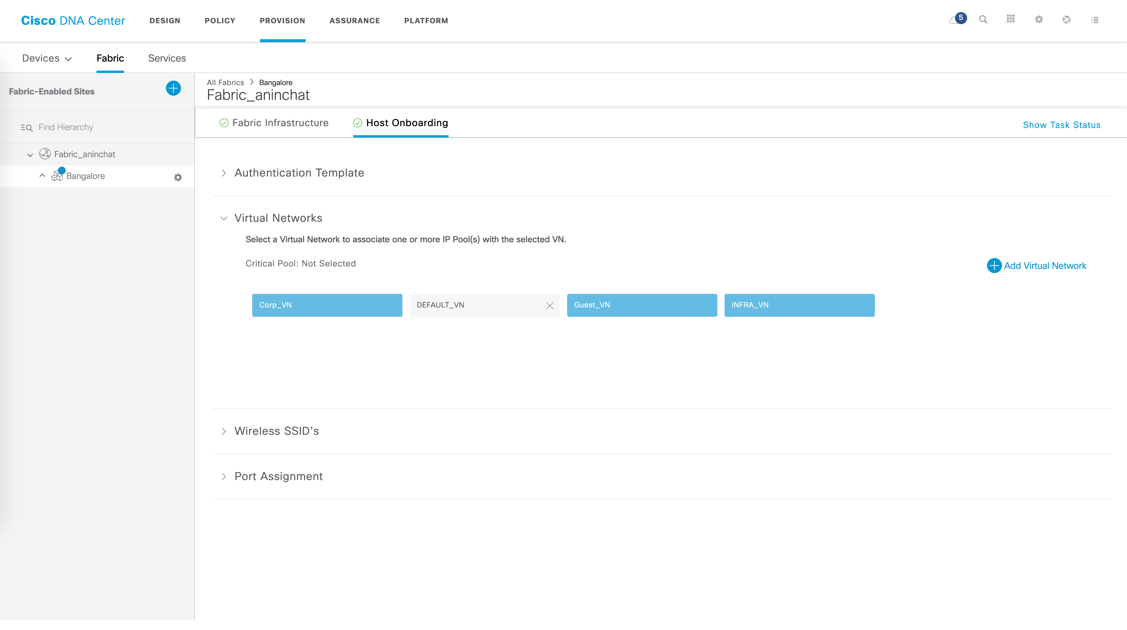
Multiple drop downs are available here - one of them is “Virtual Networks”. Here, you should see your new VN. This is also where you associate IP pools to your VNs. For example, within the VN named “Corp_VN”, I have the following IP pools associated:
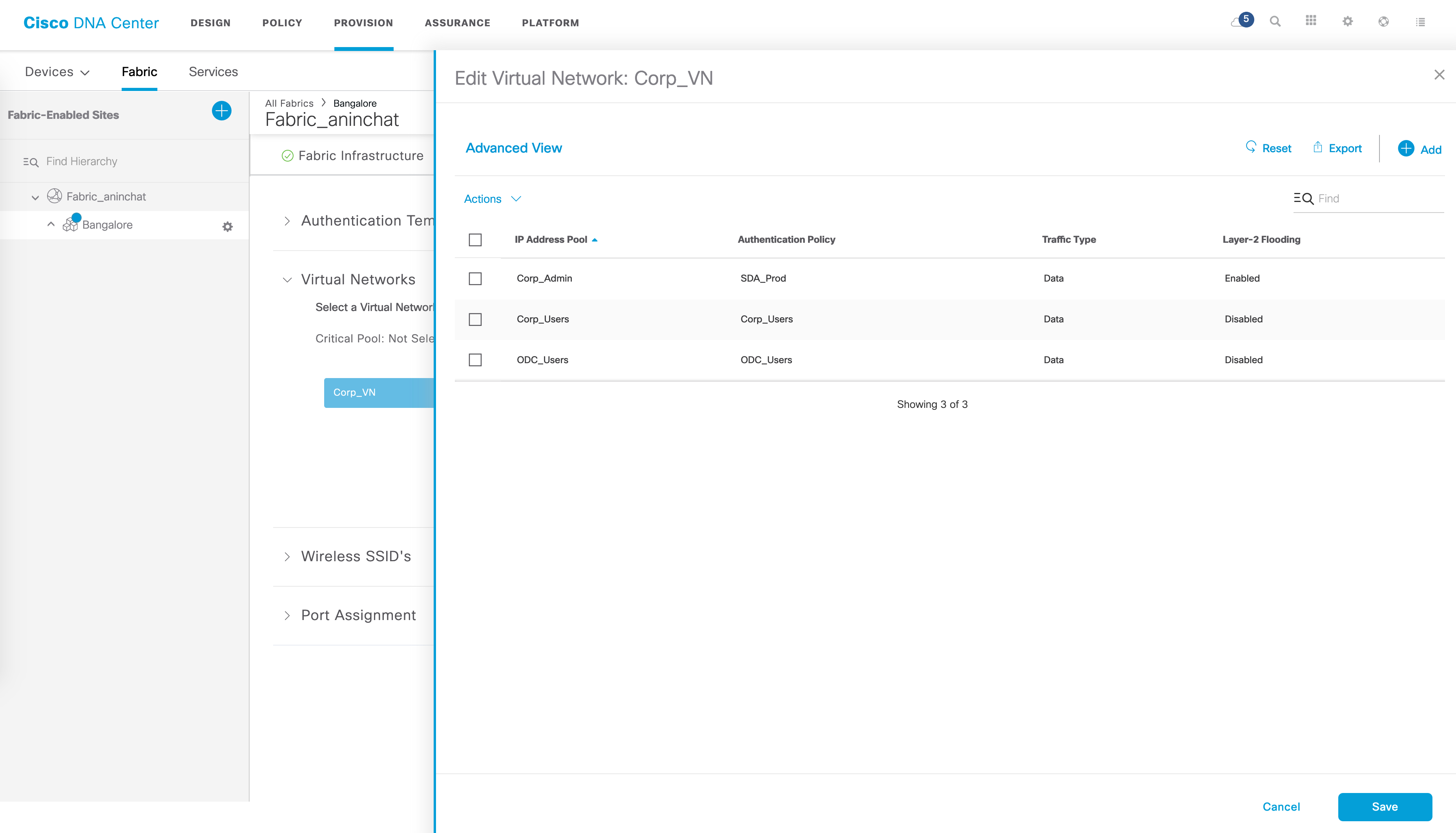
Quick tip - hovering over the name of the pool will display the actual IP subnet associated with the pool.
You can add an IP pool to your VN by clicking on the “Add” option. This gets you to the following page where you can choose your IP pool, give a name for the Authentication Policy and specify whether the traffic in this pool is data or voice. There are some other options available as well which we’re not going to get into since it is irrelevant to this post.
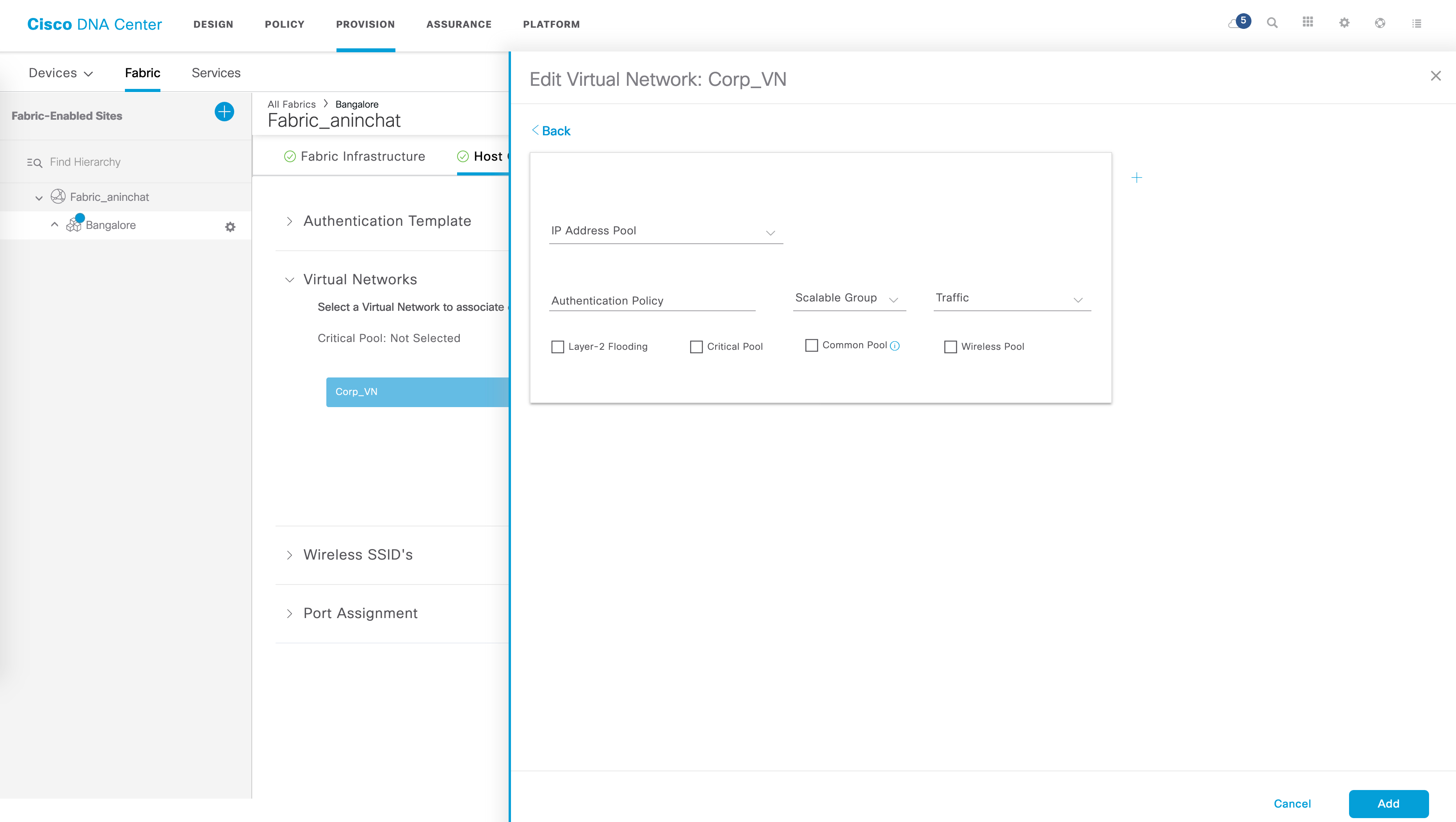
The “Authentication Policy” name is very important - this is what you use in your ISE authorization policies. We’ll get to this in part II of this series.
Once a VN is created and saved, DNAC pushes the relevant network components that are needed to make this work in the SD-Access architecture - this includes creating a L2 VLAN for this pool across all Edges, a corresponding SVI with an anycast IP address across all Edges, creating an instance-ID in LISP and other relevant LISP configuration and so on. In this setup, let’s quickly take the IP pool called “Corp_Users” to demonstrate some of this configuration.
// L2 VLAN

Edge1#show vlan name Corp_Users

VLAN Name                             Status    Ports
---- -------------------------------- --------- -------------------------------
1029 Corp_Users                       active    Tu1:8198, Gi1/0/22, Gi1/0/23

VLAN Type  SAID       MTU   Parent RingNo BridgeNo Stp  BrdgMode Trans1 Trans2
---- ----- ---------- ----- ------ ------ -------- ---- -------- ------ ------
1029 enet  101029     1500  -      -      -        -    -        0      0

Remote SPAN VLAN
----------------
Disabled

Primary Secondary Type              Ports
------- --------- ----------------- ------------------------------------------

// anycast SVI which acts as the anycast gateway

Edge1#show run int vlan 1029
Building configuration...

Current configuration : 304 bytes
!
interface Vlan1029
 description Configured from Cisco DNA-Center
 mac-address 0000.0c9f.f464
 vrf forwarding Corp_VN
 ip address 192.2.31.1 255.255.255.0
 ip helper-address 172.16.24.13
 no ip redirects
 ip route-cache same-interface
 no lisp mobility liveness test
 lisp mobility Corp_Users-IPV4
end

// LISP configuration

Edge1#show run | sec router lisp

 *snip*

 !
 instance-id 4100
  remote-rloc-probe on-route-change
  dynamic-eid Corp_Users-IPV4
   database-mapping 192.2.31.0/24 locator-set rloc_70ac0729-86f6-44d0-a1c9-254b98507c24
   exit-dynamic-eid
  !
  service ipv4
   eid-table vrf Corp_VN
   map-cache 0.0.0.0/0 map-request
   exit-service-ipv4
  !
  exit-instance-id

*snip*
Notice how the LISP instance-ID is also mapped to the VRF. This is VRF aware LISP, which forms the basis of macro segmentation.
Naturally, this subnet needs to be advertised out to the external world - for this, an aggregate is created on the Borders.
Border1#show run | sec router bgp
router bgp 65003

*snip*

 !
 address-family ipv4 vrf Corp_VN
  bgp aggregate-timer 0
  network 192.2.11.1 mask 255.255.255.255
  network 192.2.31.1 mask 255.255.255.255
  network 192.2.51.1 mask 255.255.255.255
  network 192.2.100.12 mask 255.255.255.252
  aggregate-address 192.2.51.0 255.255.255.0 summary-only
  aggregate-address 192.2.31.0 255.255.255.0 summary-only
  aggregate-address 192.2.11.0 255.255.255.0 summary-only

*snip*
Now that we have an understanding of what happens when a VN is created, let’s look at why or rather how these VNs provide segmentation. For this use case, let’s assume that all hosts (Host2, Host4 and Host5) have already been authenticated and assigned their respective VLANs and thus, their respective VNs (we will look at the authentication piece of this, along with SGTs in the next post).
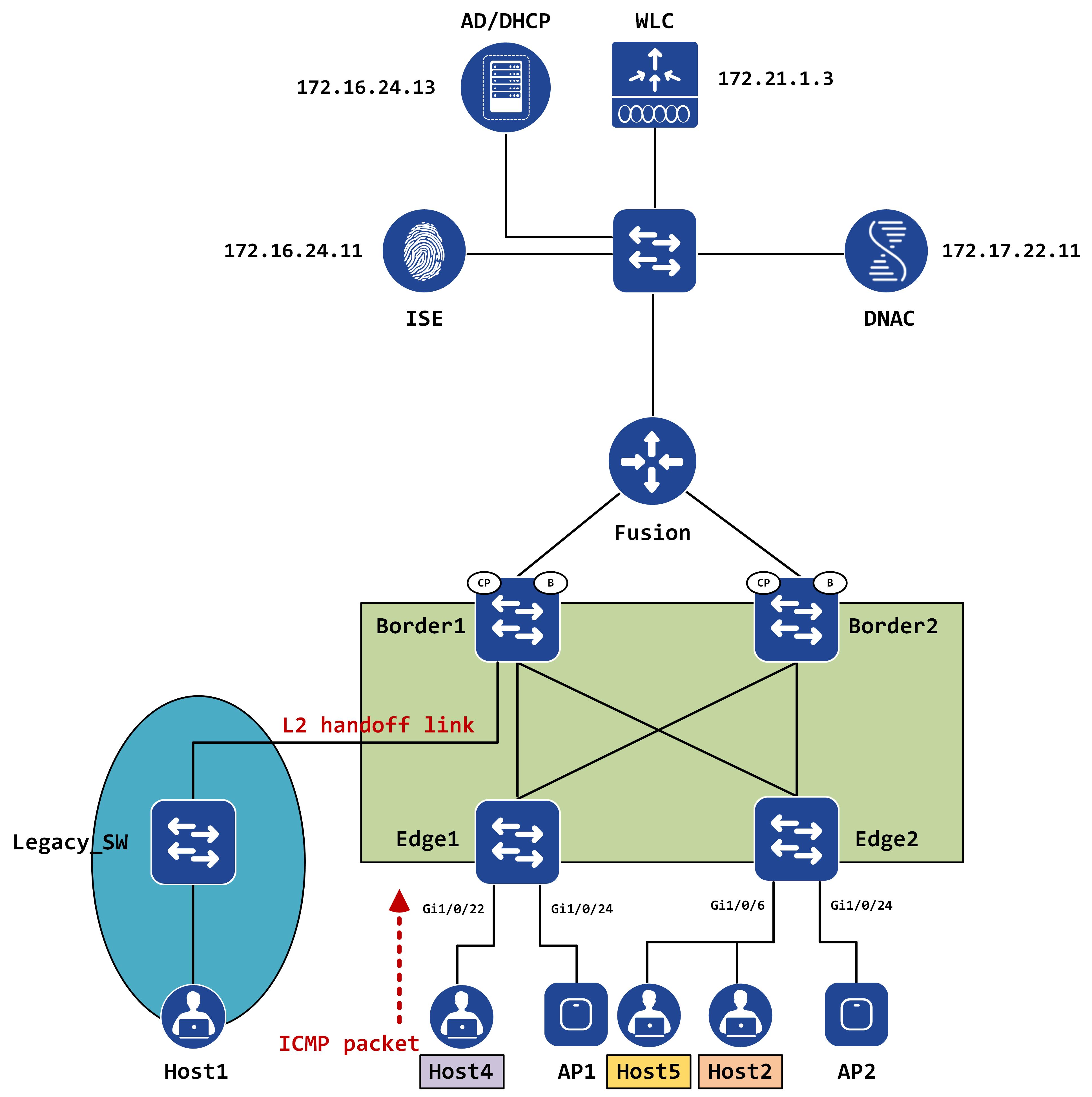
The following topology now shows the updated IPs of these hosts:
Say, Host4 (in Corp_VN) wants to reach Host5 (in Guest_VN). Since they are in two different subnets, Host4 ARPs for its default gateway (which is Edge1) and once successfully resolved, it sends the ICMP packet to Edge1.
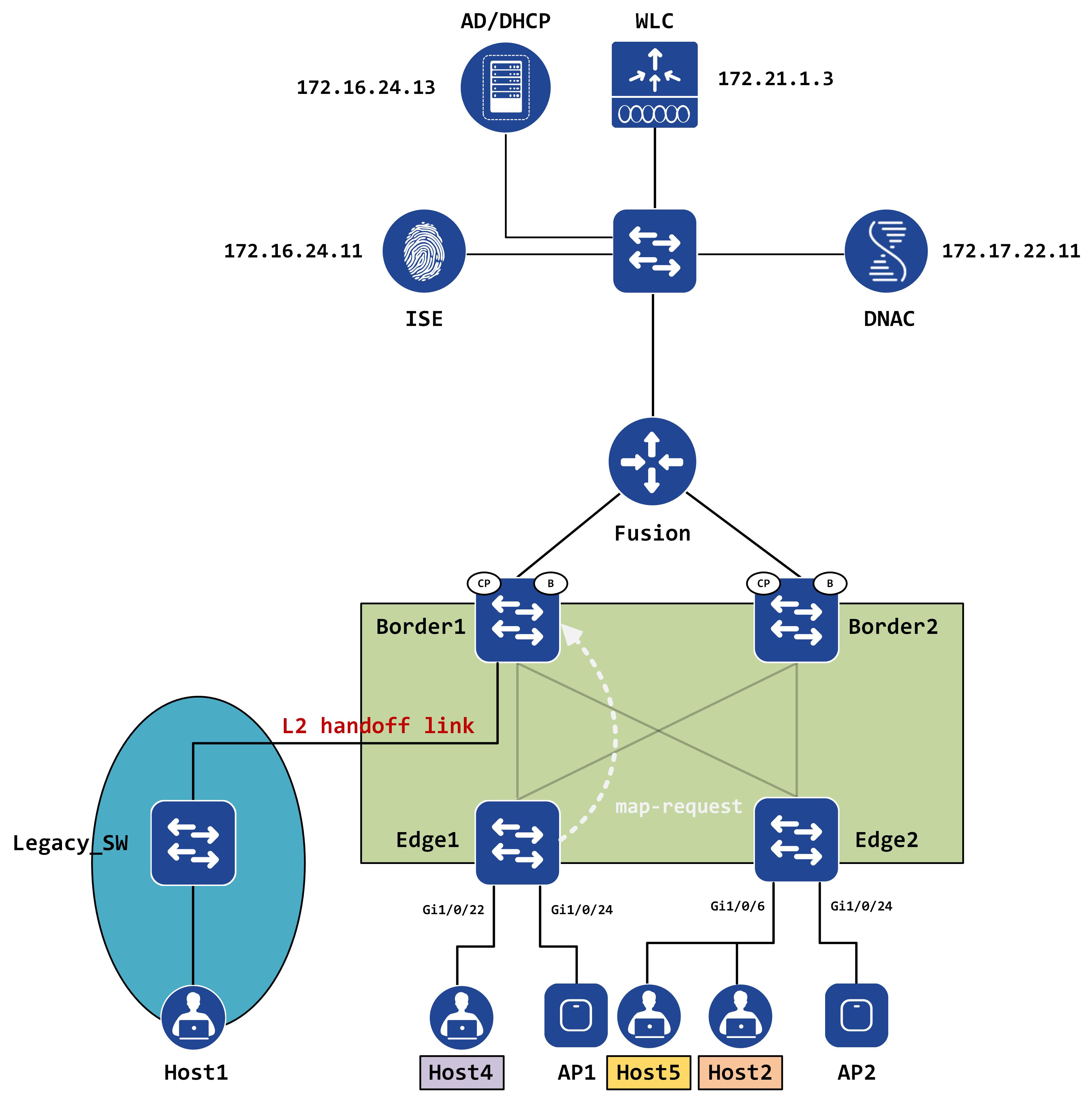
Edge1 will look at its LISP map-cache and hit the 0.0.0.0/0 entry, which says send map-request.
Edge1#show lisp instance-id 4100 ipv4 map-cache 192.2.21.2
LISP IPv4 Mapping Cache for EID-table vrf Corp_VN (IID 4100), 5 entries

0.0.0.0/0, uptime: 3w5d, expires: never, via static-send-map-request
  Sources: static-send-map-request
  State: send-map-request, last modified: 3w5d, map-source: local
  Exempt, Packets out: 854(482293 bytes) (~ 00:01:23 ago)
  Configured as EID address space
  Negative cache entry, action: send-map-request
It sends a LISP map-request to the map-resolver (Border1, in this case).
Remember, all of these packets are VRF specific. How are the VRFs identified? Using LISP instance-IDs. Each instance-ID uniquely maps to a VRF. A packet capture clearly confirms that the instance-ID is carried in map-requests as well:
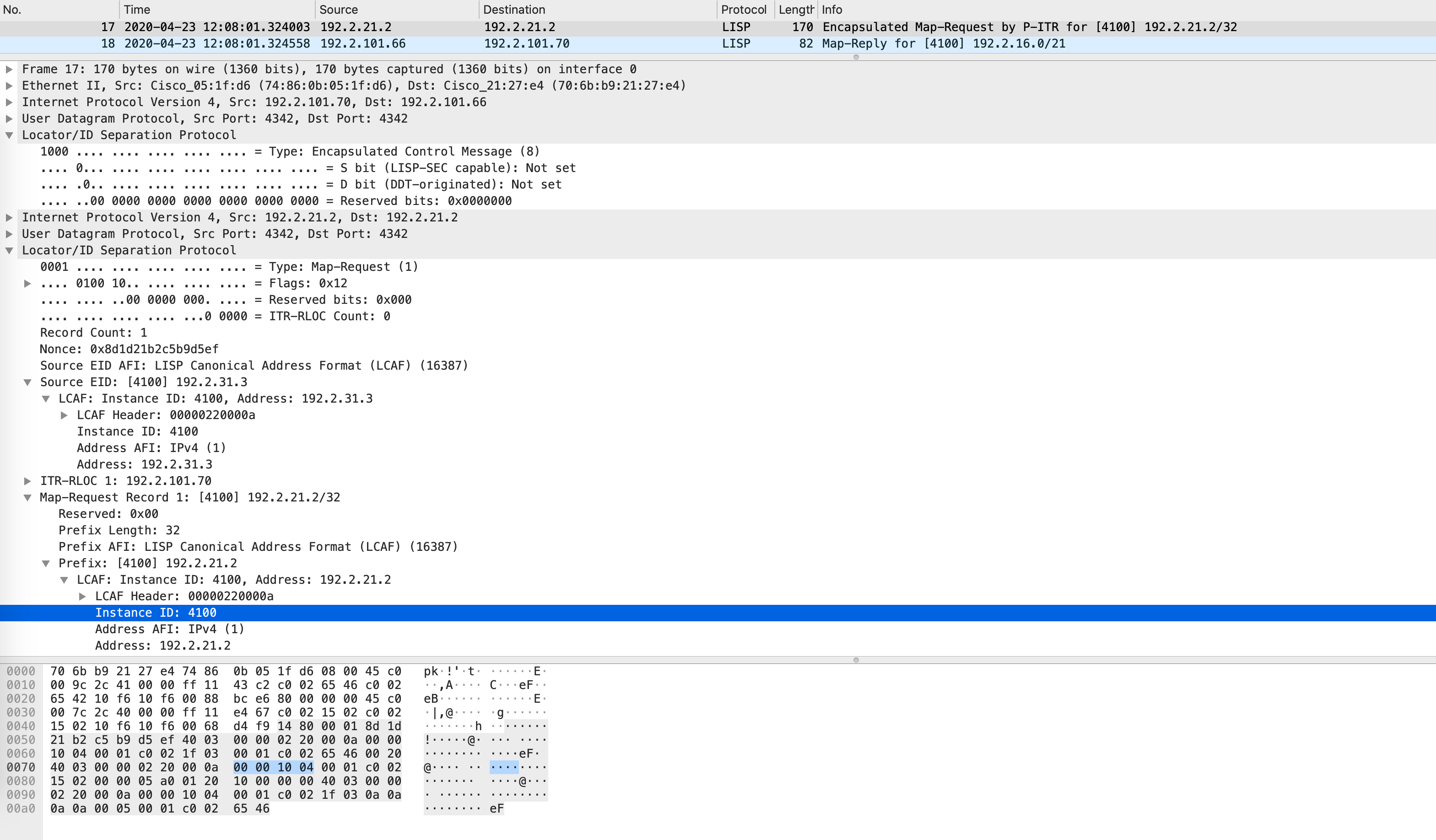
This implies that the map-resolver will look for this prefix in the corresponding instance-ID only. Does Border1 know of this subnet or this prefix in instance-ID 4100?
Border1#show lisp instance-id 4100 ipv4 server 192.2.21.2
% Could not find instance-id 4100 EID 192.2.21.2 in site database.
Nope! Border1 will now send a negative map-reply with the shortest possible subnet mask that doesn’t overlap with any other EID it knows.
This is confirmed by the following packet:
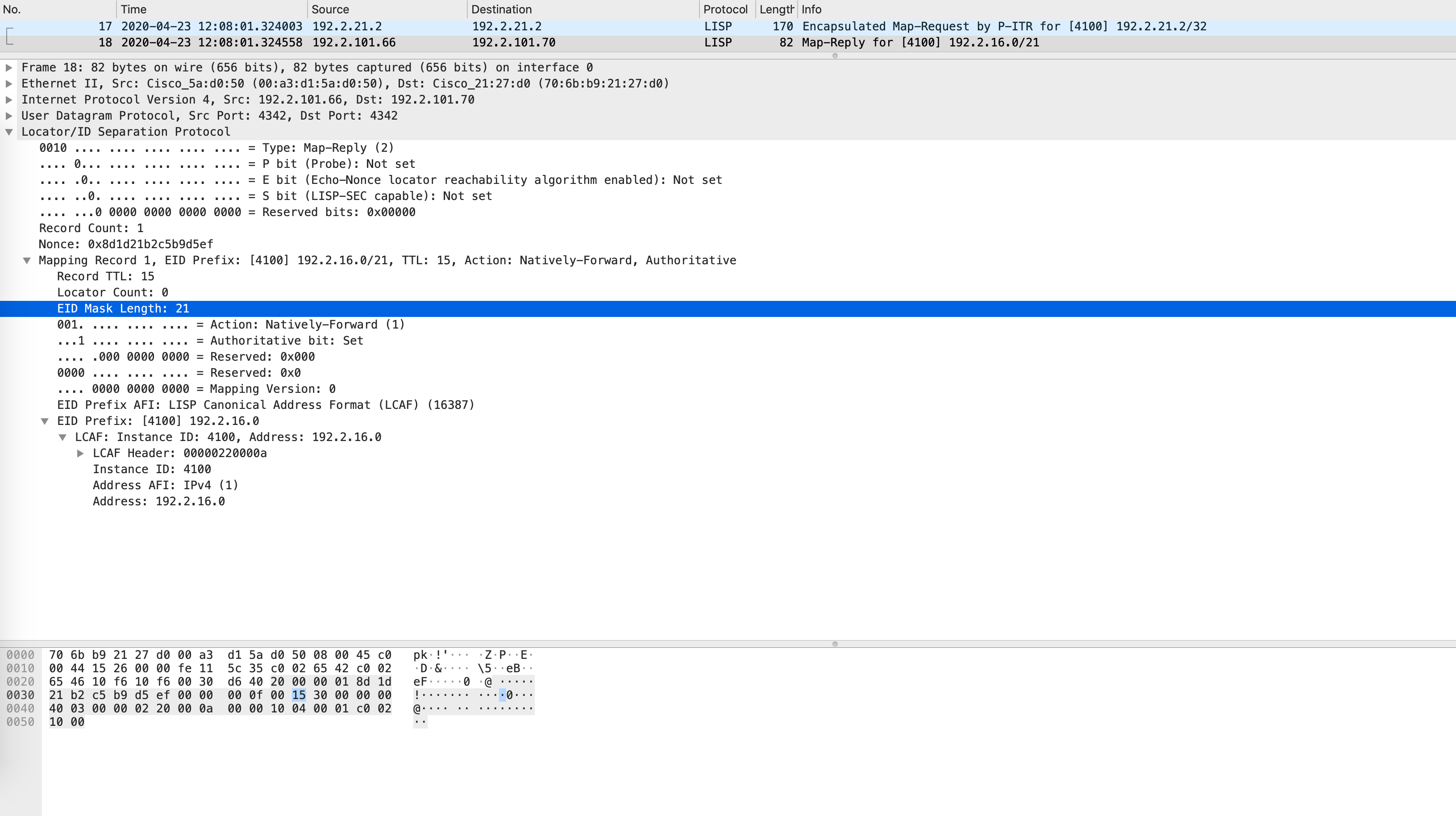
Notice the EID prefix and the EID mask - it is 192.2.16.0/21. This should now be installed in the LISP map-cache and eventually FIB on Edge1:
// LISP map-cache

Edge1#show lisp instance-id 4100 ipv4 map-cache 192.2.21.2
LISP IPv4 Mapping Cache for EID-table vrf Corp_VN (IID 4100), 6 entries

192.2.16.0/21, uptime: 00:00:03, expires: 00:14:56, via map-reply, forward-native
  Sources: map-reply
  State: forward-native, last modified: 00:00:03, map-source: 192.2.101.66
  Active, Packets out: 0(0 bytes)
  Encapsulating to proxy ETR

// FIB table

Edge1#show ip cef vrf Corp_VN 192.2.21.2 detail
192.2.16.0/21, epoch 0, flags [subtree context, check lisp eligibility], per-destination sharing
  SC owned,sourced: LISP remote EID - locator status bits 0x00000000
  LISP remote EID: 3 packets 1728 bytes fwd action encap, cfg as EID space
  LISP source path list
    nexthop 192.2.101.65 LISP0.4100
    nexthop 192.2.101.66 LISP0.4100
  2 IPL sources [no flags]
  nexthop 192.2.101.65 LISP0.4100
  nexthop 192.2.101.66 LISP0.4100
Edge1 encapsulates this and sends it to Border1 (or Border2) but where would they send the packet to? It will simply get blackholed on the borders.
This is why you need a fusion device - to facilitate conversation between VNs (the cleanest way of doing this, for shared services, would be LISP Extranet but that feature is still not available in SD-Access). You form a VRF-lite style BGP peering per VN (or VRF) towards your fusion device - this can be automated via the L3 handoff feature of DNAC.
However, since the packet is decapsulated at the border, you end up losing the VXLAN header and thus the VNI and the SGT as well.
This implies that with the addition of a fusion, you now have no restrictions in conversation between VNs which was the whole point of macro-segmentation. Sounds counter-intuitive, doesn’t it? This is why a lot of customers will use a firewall as a fusion so that firewall rules can control inter-VN communication. Alternatively, we can use static IP-SGT mappings on the borders to control this as well using SXP tunnels. This is something we’ll cover in the micro-segmentation post.
So, there we have it - macro-segmentation in all its glorious beauty. I hope this was informative, see y’all in the next one!