Cumulus Basics Part VI - VXLAN L2VNIs with BGP EVPN
In this post, we introduce BGP EVPN and a VXLAN fabric in Cumulus Linux, with L2VNIs.
Introduction
Now that we’ve covered the basics of BGP unnumbered in the last post, we’ll start building a VXLAN based fabric with BGP EVPN.
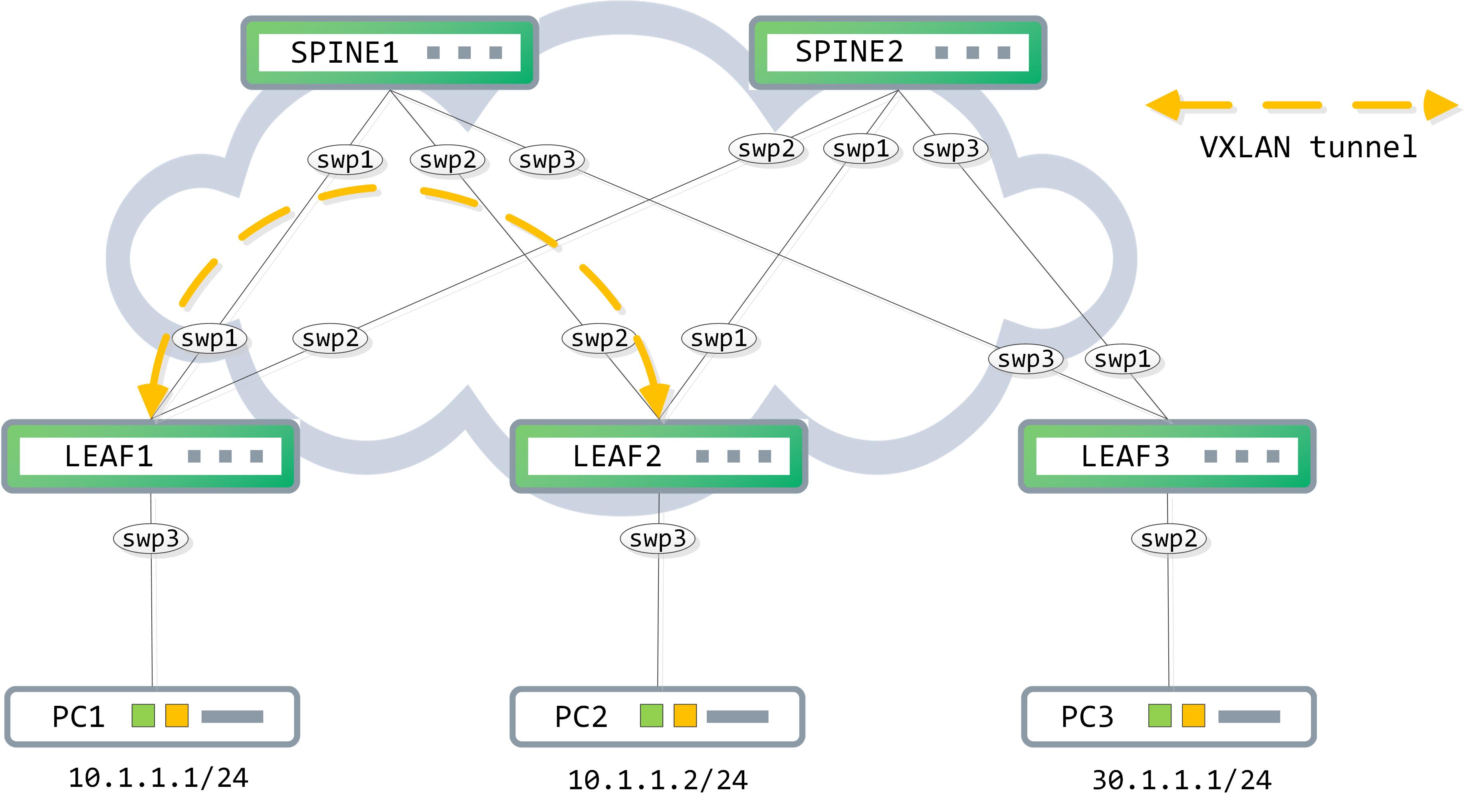
Topology
Our topology remains the same, with a minor change - PC2 has now been moved to the same subnet as PC1, 10.1.1.0/24:
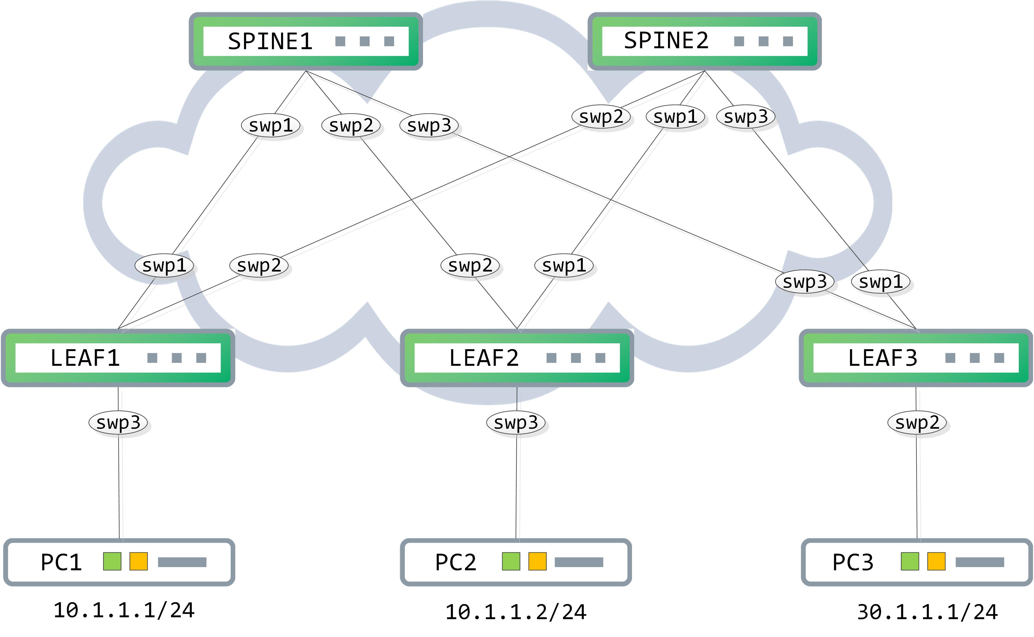
The PCs are lightweight emulations here. Take note of the mac addresses assigned to them as they will be important and constantly referenced through the post:
PC1> show ip

NAME        : PC1[1]
IP/MASK     : 10.1.1.1/24
GATEWAY     : 10.1.1.254
DNS         :
MAC         : 00:50:79:66:68:06
LPORT       : 20000
RHOST:PORT  : 127.0.0.1:30000
MTU         : 1500

PC2> show ip

NAME        : PC2[1]
IP/MASK     : 10.1.1.2/24
GATEWAY     : 10.1.1.254
DNS         :
MAC         : 00:50:79:66:68:07
LPORT       : 20000
RHOST:PORT  : 127.0.0.1:30000
MTU         : 1500
Start by activating the neighbors against the L2VPN EVPN AFI/SAFI. Outside of this, I am re-doing some of the configurations from the previous post for completeness sake. We are adding a loopback per switch, adding BGP neighbors and marking each LEAF switch as a route reflector client on the SPINEs
// SPINE1

cumulus@SPINE1:~$ net add loopback lo ip address 11.11.11.11/32
cumulus@SPINE1:~$ net add bgp autonomous-system 1
cumulus@SPINE1:~$ net add bgp neighbor swp1-3 remote-as internal
cumulus@SPINE1:~$ net add bgp neighbor swp1-3 route-reflector-client
cumulus@SPINE1:~$ net add bgp l2vpn evpn neighbor swp1-3 activate
cumulus@SPINE1:~$ net add bgp l2vpn evpn neighbor swp1-3 route-reflector-client

// SPINE2

cumulus@SPINE2:~$ net add loopback lo ip address 22.22.22.22/32
cumulus@SPINE2:~$ net add bgp autonomous-system 1
cumulus@SPINE2:~$ net add bgp neighbor swp1-3 remote-as internal
cumulus@SPINE2:~$ net add bgp neighbor swp1-3 route-reflector-client
cumulus@SPINE2:~$ net add bgp l2vpn evpn neighbor swp1-3 activate
cumulus@SPINE2:~$ net add bgp l2vpn evpn neighbor swp1-3 route-reflector-client

// LEAF1

cumulus@LEAF1:~$ net add loopback lo ip add 1.1.1.1/32
cumulus@LEAF1:~$ net add bgp autonomous-system 1
cumulus@LEAF1:~$ net add bgp neighbor swp1-2 remote-as internal
cumulus@LEAF1:~$ net add bgp l2vpn evpn neighbor swp1-2 activate
cumulus@LEAF1:~$ net commit
The LEAF1 configuration must be appropriately replicated on the other two LEAF switches (modify interfaces as needed and add unique loopback IPs).
Post this, confirm that BGP peerings for L2VPN EVPN is up. Each SPINE should have three peerings, one to each LEAF switch:
// SPINE1 peerings:

cumulus@SPINE1:~$ net show bgp l2vpn evpn summary
BGP router identifier 11.11.11.11, local AS number 1 vrf-id 0
BGP table version 0
RIB entries 0, using 0 bytes of memory
Peers 3, using 58 KiB of memory

Neighbor        V         AS MsgRcvd MsgSent   TblVer  InQ OutQ  Up/Down State/PfxRcd
LEAF1(swp1)     4          1      63      64        0    0    0 00:02:57            0
LEAF2(swp2)     4          1      42      43        0    0    0 00:01:56            0
LEAF3(swp3)     4          1      29      30        0    0    0 00:01:16            0

Total number of neighbors 3

// SPINE2 peerings:

cumulus@SPINE2:~$ net show bgp l2vpn evpn summary
BGP router identifier 22.22.22.22, local AS number 1 vrf-id 0
BGP table version 0
RIB entries 0, using 0 bytes of memory
Peers 3, using 58 KiB of memory

Neighbor        V         AS MsgRcvd MsgSent   TblVer  InQ OutQ  Up/Down State/PfxRcd
LEAF2(swp1)     4          1      47      48        0    0    0 00:02:10            0
LEAF1(swp2)     4          1      70      71        0    0    0 00:03:19            0
LEAF3(swp3)     4          1      36      36        0    0    0 00:01:38            0

Total number of neighbors 3
Remember that the underlay provides reachability from one tunnel endpoint to another. Since we are using BGP unnumbered as the underlay itself, we need to advertise the loopbacks of each LEAF switch into the IPv4 address family.
// LEAF1

cumulus@LEAF1:~$ net add bgp network 1.1.1.1/32
cumulus@LEAF1:~$ net commit

// LEAF2

cumulus@LEAF2:~$ net add bgp network 2.2.2.2/32
cumulus@LEAF2:~$ net commit

// LEAF3

cumulus@LEAF3:~$ net add bgp network 3.3.3.3/32
cumulus@LEAF3:~$ net commit
Each LEAF switch should now be aware of the loopbacks of the other to LEAF switches.
// LEAF1

cumulus@LEAF1:~$ net show bgp ipv4 unicast
BGP table version is 7, local router ID is 1.1.1.1
Status codes: s suppressed, d damped, h history, * valid, > best, = multipath,
              i internal, r RIB-failure, S Stale, R Removed
Origin codes: i - IGP, e - EGP, ? - incomplete

   Network          Next Hop            Metric LocPrf Weight Path
*> 1.1.1.1/32       0.0.0.0                  0         32768 i
*=i2.2.2.2/32       swp2                     0    100      0 i
*>i                 swp1                     0    100      0 i
*=i3.3.3.3/32       swp2                     0    100      0 i
*>i                 swp1                     0    100      0 i

Displayed  3 routes and 5 total paths

// LEAF2

cumulus@LEAF2:~$ net show bgp ipv4 unicast
BGP table version is 6, local router ID is 2.2.2.2
Status codes: s suppressed, d damped, h history, * valid, > best, = multipath,
              i internal, r RIB-failure, S Stale, R Removed
Origin codes: i - IGP, e - EGP, ? - incomplete

   Network          Next Hop            Metric LocPrf Weight Path
*>i1.1.1.1/32       swp2                     0    100      0 i
*=i                 swp1                     0    100      0 i
*> 2.2.2.2/32       0.0.0.0                  0         32768 i
*>i3.3.3.3/32       swp2                     0    100      0 i
*=i                 swp1                     0    100      0 i

Displayed  3 routes and 5 total paths

// LEAF3

cumulus@LEAF3:~$ net show bgp ipv4 unicast
BGP table version is 6, local router ID is 3.3.3.3
Status codes: s suppressed, d damped, h history, * valid, > best, = multipath,
              i internal, r RIB-failure, S Stale, R Removed
Origin codes: i - IGP, e - EGP, ? - incomplete

   Network          Next Hop            Metric LocPrf Weight Path
*>i1.1.1.1/32       swp3                     0    100      0 i
*=i                 swp1                     0    100      0 i
*>i2.2.2.2/32       swp3                     0    100      0 i
*=i                 swp1                     0    100      0 i
*> 3.3.3.3/32       0.0.0.0                  0         32768 i

Displayed  3 routes and 5 total paths
Confirm reachability from loopback to loopback. Running this test from one of the LEAF switches should be enough:
// LEAF1 to LEAF2 reachability

cumulus@LEAF1:~$ ping 2.2.2.2 -I 1.1.1.1
PING 2.2.2.2 (2.2.2.2) from 1.1.1.1 : 56(84) bytes of data.
64 bytes from 2.2.2.2: icmp_seq=1 ttl=63 time=1.94 ms
64 bytes from 2.2.2.2: icmp_seq=2 ttl=63 time=2.05 ms
64 bytes from 2.2.2.2: icmp_seq=3 ttl=63 time=2.73 ms
64 bytes from 2.2.2.2: icmp_seq=4 ttl=63 time=1.91 ms
64 bytes from 2.2.2.2: icmp_seq=5 ttl=63 time=1.01 ms
^C
--- 2.2.2.2 ping statistics ---
5 packets transmitted, 5 received, 0% packet loss, time 4008ms
rtt min/avg/max/mdev = 1.012/1.931/2.730/0.550 ms

// LEAF1 to LEAF3 reachability

cumulus@LEAF1:~$ ping 3.3.3.3 -I 1.1.1.1
PING 3.3.3.3 (3.3.3.3) from 1.1.1.1 : 56(84) bytes of data.
64 bytes from 3.3.3.3: icmp_seq=1 ttl=63 time=18.2 ms
64 bytes from 3.3.3.3: icmp_seq=2 ttl=63 time=1.78 ms
64 bytes from 3.3.3.3: icmp_seq=3 ttl=63 time=2.41 ms
64 bytes from 3.3.3.3: icmp_seq=4 ttl=63 time=1.85 ms
64 bytes from 3.3.3.3: icmp_seq=5 ttl=63 time=2.28 ms
^C
--- 3.3.3.3 ping statistics ---
5 packets transmitted, 5 received, 0% packet loss, time 4008ms
rtt min/avg/max/mdev = 1.788/5.314/18.230/6.462 ms
Now, we start with a simple premise - PC1 cannot ping PC2:
PC1> ping 10.1.1.2

host (10.1.1.2) not reachable
Our goal is to allow PC1 to talk to PC2 via a VXLAN fabric. The idea is straightforward - you map your VLAN to a VNID (VXLAN network ID) and associate this to a virtual interface that acts as your entry/exit point for VXLAN packets.
The configuration on a Cumulus box for this is like so (scroll right to understand what each configuration is doing):
cumulus@LEAF1:~$ net add vxlan vni10 vxlan id 10010 			// adds VNID to virtual interface, vni10
cumulus@LEAF1:~$ net add vxlan vni10 bridge access 10			// adds VLAN 10 to vni10
cumulus@LEAF1:~$ net add vxlan vni10 bridge learning off		// disables mac learning on vni10
cumulus@LEAF1:~$ net add vxlan vni10 vxlan local-tunnelip 1.1.1.1	// specifies local source IP to be 1.1.1.1 for VXLAN packets
It is also important to understand what changes the above commands translate to, so take a look at that when you commit them:
cumulus@LEAF1:~$ net commit
--- /etc/network/interfaces     2019-05-13 05:23:36.667000000 +0000
+++ /run/nclu/ifupdown2/interfaces.tmp  2019-05-13 05:29:13.613000000 +0000
@@ -18,20 +18,29 @@

 auto swp2
 iface swp2

 auto swp3
 iface swp3
     bridge-access 10

 auto bridge
 iface bridge
-    bridge-ports swp3
+    bridge-ports swp3 vni10
     bridge-vids 10
     bridge-vlan-aware yes

 auto vlan10
 iface vlan10
     address 10.1.1.254/24
     vlan-id 10
     vlan-raw-device bridge

+auto vni10
+iface vni10
+    bridge-access 10
+    bridge-learning off
+    mstpctl-bpduguard yes
+    mstpctl-portbpdufilter yes
+    vxlan-id 10010
+    vxlan-local-tunnelip 1.1.1.1
+


net add/del commands since the last "net commit"
================================================

User     Timestamp                   Command
-------  --------------------------  ------------------------------------------------
cumulus  2019-05-13 05:27:26.613573  net add vxlan vni10 vxlan id 10010
cumulus  2019-05-13 05:28:16.336833  net add vxlan vni10 bridge access 10
cumulus  2019-05-13 05:28:27.454434  net add vxlan vni10 bridge learning off
cumulus  2019-05-13 05:29:08.227404  net add vxlan vni10 vxlan local-tunnelip 1.1.1.1
The changes we made creates a new virtual interface with the name ‘vni10’ (we gave this name in the first command), associates VLAN 10 and a VXLAN network identifier (VNID) of 10010 to it, disables mac learning on this, associates a source IP of 1.1.1.1 to this and adds this interface to the VLAN-aware bridge.
Mimic this configuration on LEAF2 - the only change you need to make there is the local tunnel-ip that is used (configure that as LEAF2s loopback, 2.2.2.2).
Control-plane flow
Let’s try and understand the flow of control-plane learning now. As a baseline, we have not learnt PC1/PC2 macs nor are there any type-2 routes in the BGP table:
// LEAF1

cumulus@LEAF1:~$ net show bridge macs vlan 10

VLAN  Master  Interface  MAC                TunnelDest  State      Flags  LastSeen
----  ------  ---------  -----------------  ----------  ---------  -----  --------
  10  bridge  bridge     50:00:00:04:00:03              permanent         02:40:27

cumulus@LEAF1:~$ net show bgp l2vpn evpn route type macip
No EVPN prefixes (of requested type) exist

// LEAF2

cumulus@LEAF2:~$ net show bridge macs vlan 10

VLAN  Master  Interface  MAC                TunnelDest  State      Flags  LastSeen
----  ------  ---------  -----------------  ----------  ---------  -----  --------
  10  bridge  bridge     50:00:00:05:00:03              permanent         02:40:41

cumulus@LEAF2:~$ net show bgp l2vpn evpn route type macip
No EVPN prefixes (of requested type) exist
I am going to restart PC1 now. This forces a GARP to be sent out when it comes up and this GARP causes PC1s mac to be learnt on swp3 of LEAF1:
cumulus@LEAF1:~$ net show bridge macs vlan 10

VLAN  Master  Interface  MAC                TunnelDest  State      Flags  LastSeen
----  ------  ---------  -----------------  ----------  ---------  -----  --------
  10  bridge  bridge     50:00:00:04:00:03              permanent         02:49:50
  10  bridge  swp3       00:50:79:66:68:06                                00:00:17
Once the mac is learnt, it gets pushed into the BGP table as well:
cumulus@LEAF1:~$ net show bgp l2vpn evpn route type macip
BGP table version is 13, local router ID is 1.1.1.1
Status codes: s suppressed, d damped, h history, * valid, > best, i - internal
Origin codes: i - IGP, e - EGP, ? - incomplete
EVPN type-2 prefix: [2]:[ESI]:[EthTag]:[MAClen]:[MAC]:[IPlen]:[IP]
EVPN type-3 prefix: [3]:[EthTag]:[IPlen]:[OrigIP]
EVPN type-5 prefix: [5]:[ESI]:[EthTag]:[IPlen]:[IP]

   Network          Next Hop            Metric LocPrf Weight Path
Route Distinguisher: 1.1.1.1:2
*> [2]:[0]:[0]:[48]:[00:50:79:66:68:06]
                    1.1.1.1                            32768 i
*> [2]:[0]:[0]:[48]:[00:50:79:66:68:06]:[32]:[10.1.1.1]
                    1.1.1.1                            32768 i

Displayed 2 prefixes (2 paths) (of requested type)
This will now be sent as an update to the SPINEs and the SPINEs reflect it to LEAF2. A packet capture on LEAF2 shows this BGP UPDATE message:
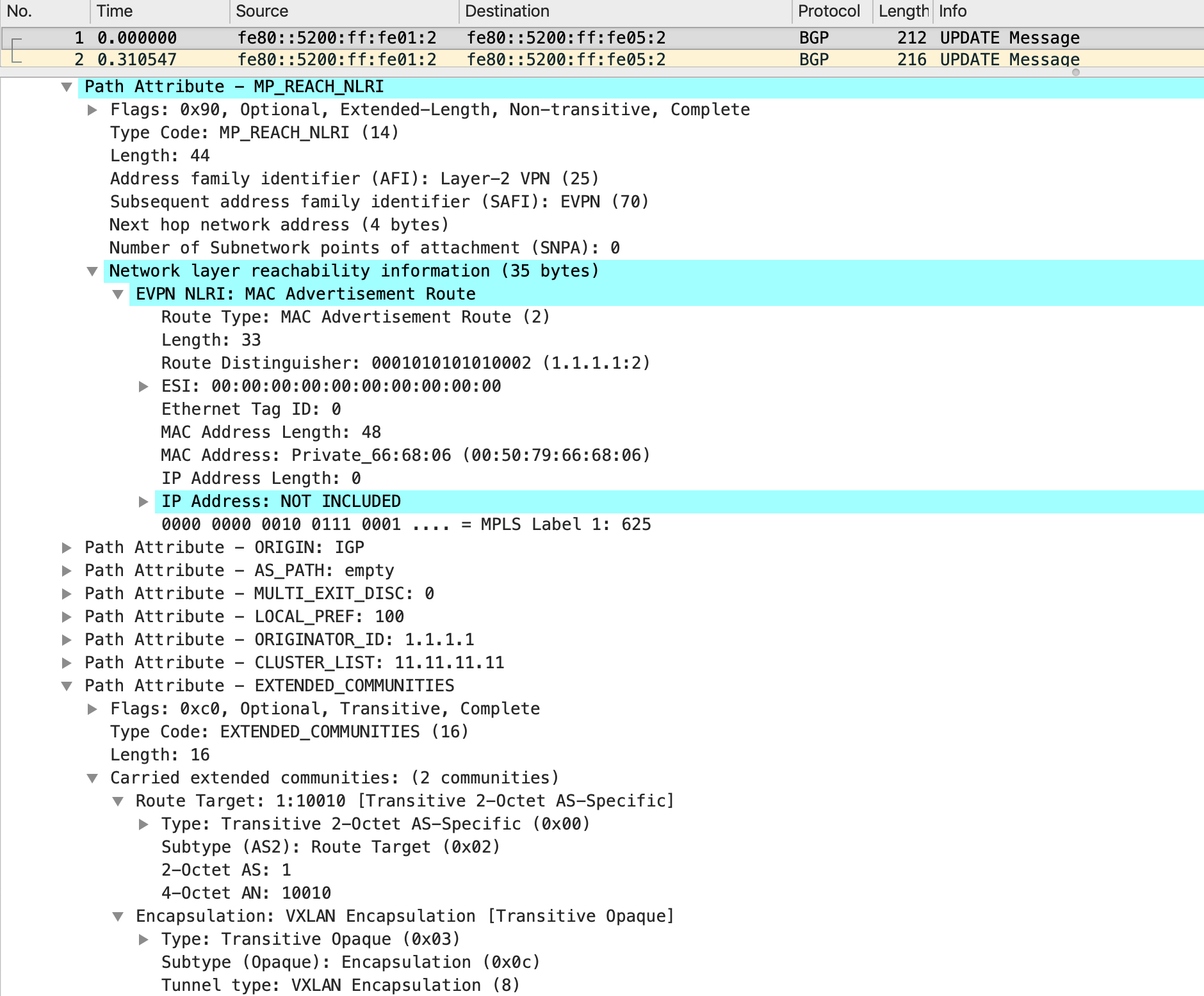
There is a lot of interesting information in this update. The NLRI is an EVPN NLRI, describing a mac advertisement route (type-2). The RD is 1.1.1.1:2 and you can see the mac address inside this NLRI with no IP address included. Also, look at the final attribute which is for extended communities - this includes the RT (which is a combination of the AS and the VNID itself). The extended community also describes the encapsulation which is of type VXLAN.
Immediately after this update, another update is sent with the IP address included this time:
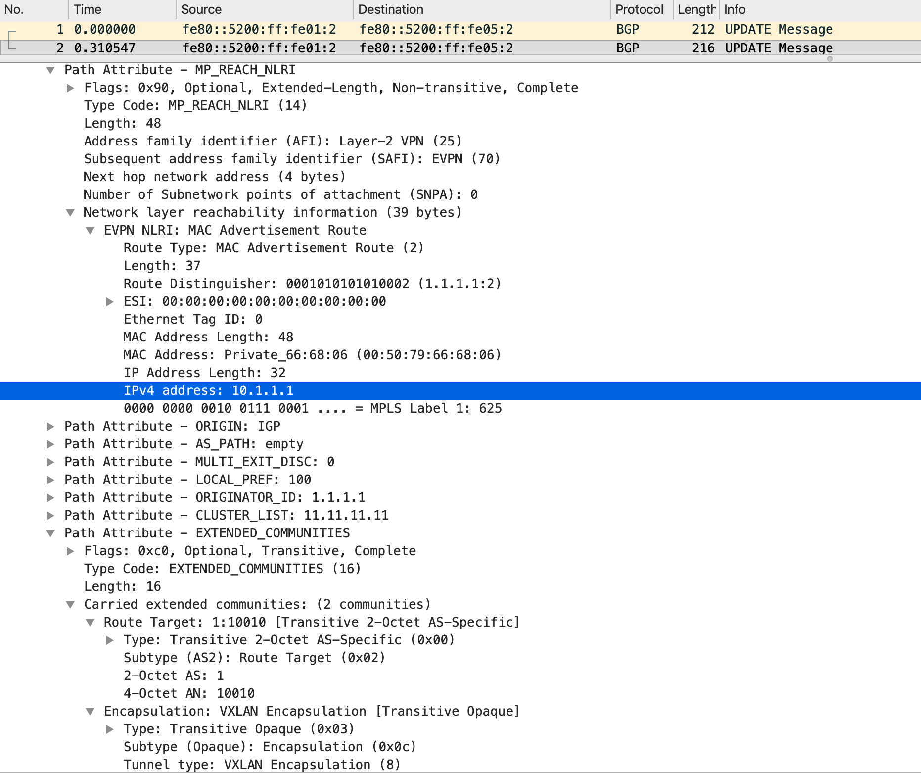
LEAF2 gets this update and installs it in its BGP table as well against the RD that was in the update (1.1.1.1:2):
cumulus@LEAF2:~$ net show bgp l2vpn evpn route type macip
BGP table version is 16, local router ID is 2.2.2.2
Status codes: s suppressed, d damped, h history, * valid, > best, i - internal
Origin codes: i - IGP, e - EGP, ? - incomplete
EVPN type-2 prefix: [2]:[ESI]:[EthTag]:[MAClen]:[MAC]:[IPlen]:[IP]
EVPN type-3 prefix: [3]:[EthTag]:[IPlen]:[OrigIP]
EVPN type-5 prefix: [5]:[ESI]:[EthTag]:[IPlen]:[IP]

   Network          Next Hop            Metric LocPrf Weight Path
Route Distinguisher: 1.1.1.1:2
*>i[2]:[0]:[0]:[48]:[00:50:79:66:68:06]
                    1.1.1.1                  0    100      0 i
*>i[2]:[0]:[0]:[48]:[00:50:79:66:68:06]:[32]:[10.1.1.1]
                    1.1.1.1                  0    100      0 i

Displayed 2 prefixes (2 paths) (of requested type)
From here, the type-2 route gets pushed into the mac address table and associated to vni10, with the ‘offload’ flag set and the VXLAN destination IP set to 1.1.1.1:
cumulus@LEAF2:~$ net show bridge macs | grep 00:50:79:66:68:06
VLAN      Master  Interface  MAC                TunnelDest  State      Flags          LastSeen
--------  ------  ---------  -----------------  ----------  ---------  -------------  --------
10        bridge  vni10      00:50:79:66:68:06                         offload        00:16:43
untagged          vni10      00:50:79:66:68:06  1.1.1.1                self, offload  00:16:43
You can see that with the BGP EVPN control-plane, the data-plane is already built and ready without any conversation between the hosts.
Data-plane flow
From a data-plane perspective, when PC1 pings PC2, it tries to resolve the IP address first. This is achieved via an ARP request that goes through the fabric. This is typically done in two ways - either with headend replication on the ingress tunnel endpoint (meaning the ARP is packaged into a unicast packet sent over the VXLAN fabric) or via multicast (the underlay needs to be multicast aware). We are not going to go into BUM (broadcast/unknown unicast/multicast) traffic handling right now since that needs to be a separate post in itself.
Assuming that ARP is resolved, PC1 generates a unicast ICMP request message that hits LEAF1. LEAF1 does a mac table lookup and finds that this needs to be sent over vni10, with a VXLAN encapsulation, a VNID of 10010 and a destination IP of 2.2.2.2:
cumulus@LEAF1:~$ net show bridge macs 00:50:79:66:68:07

VLAN      Master  Interface  MAC                TunnelDest  State  Flags          LastSeen
--------  ------  ---------  -----------------  ----------  -----  -------------  --------
10        bridge  vni10      00:50:79:66:68:07                     offload        00:59:05
untagged          vni10      00:50:79:66:68:07  2.2.2.2            self, offload  00:59:05
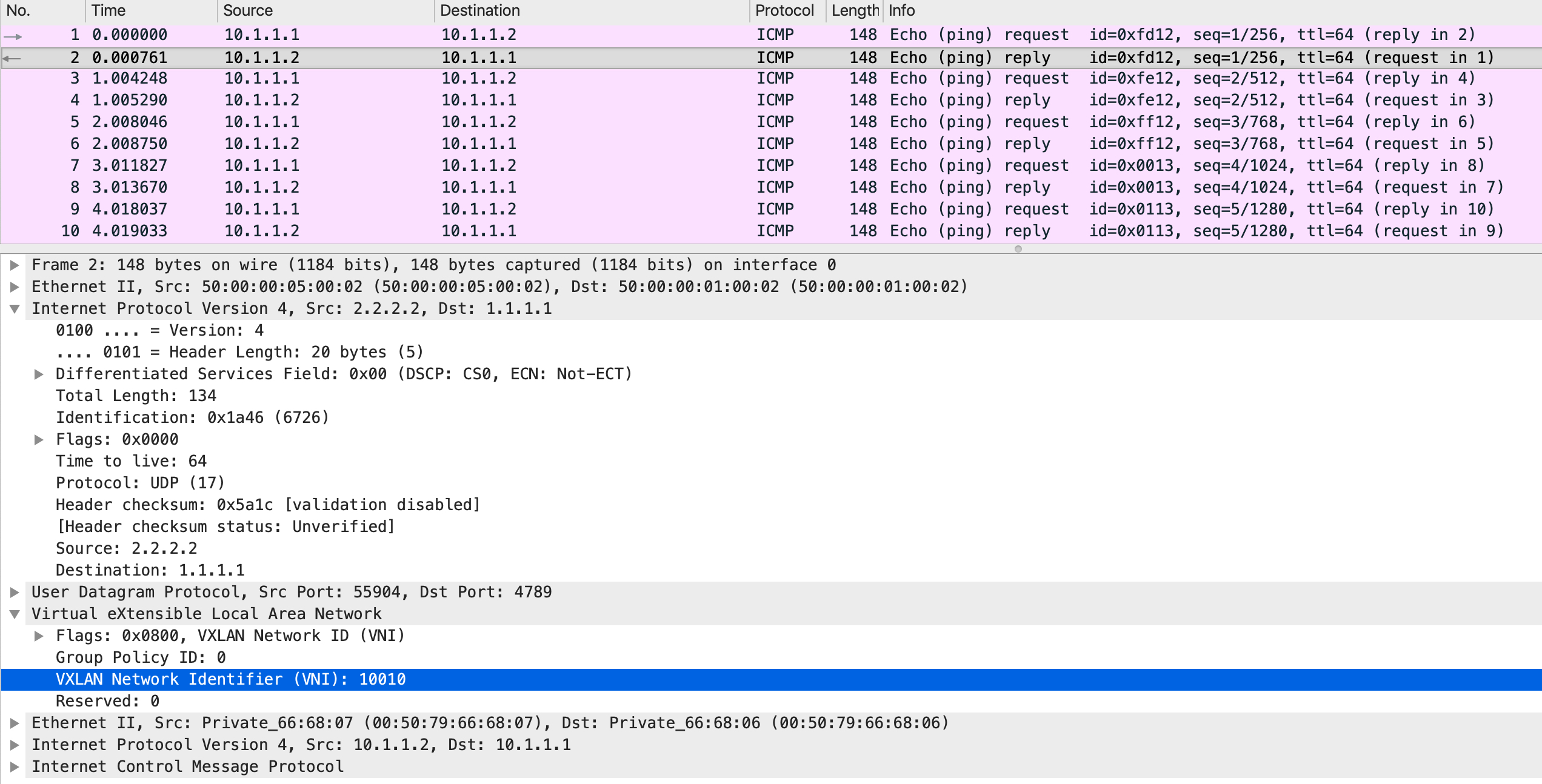
On the wire, the packets look like this:
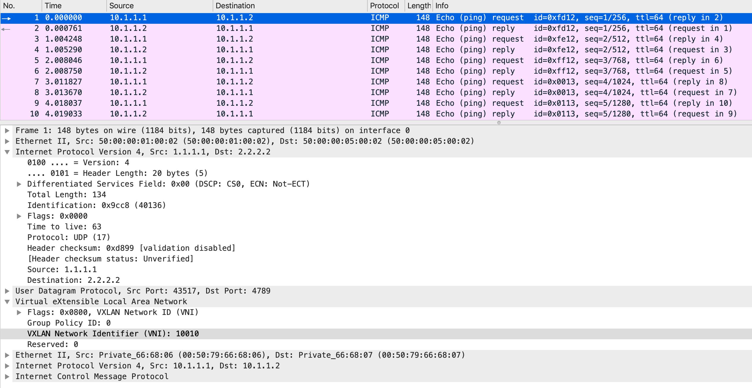
It is an ICMP header inside an IP header inside a VXLAN header inside a UDP header inside an IP header. The logic is that the top most IP header carries the packet from one VXLAN tunnel endpoint to the other. At the other end, the top most IP header is stripped off (since it owns the destination IP address), revealing the UDP and the VXLAN headers which are subsequently stripped off as well. Another mac lookup is done on the packet and a forwarding decision is made based on that:
cumulus@LEAF2:~$ net show bridge macs 00:50:79:66:68:07

VLAN  Master  Interface  MAC                TunnelDest  State  Flags  LastSeen
----  ------  ---------  -----------------  ----------  -----  -----  --------
  10  bridge  swp3       00:50:79:66:68:07                            00:00:03
In this case, the mac table says that the packet needs to be forwarded out of swp3. This gets the packet to PC2 which responds back with an ICMP reply. The entire data-plane process happens again, in the reverse direction with LEAF2 now being the source of the VXLAN encapsulation:
Notice how the top most IP header now has a source IP address of 2.2.2.2. Effectively, you can visualize this as a bi-directional tunnel carrying traffic over a routed infrastructure between two hosts in the same subnet.
I hope this was informative. I’ll see y’all in the next post!