Junos Part I - the basics
In this post, we take an introductory look at the operating system used in Juniper platforms, called Junos OS. This post serves as an introduction to the CLI. We also cover basic bridging.
Introduction and topology
As a new user of the Junos OS, I thought I’d take this opportunity to blog about what I generally start with when learning a new platform/OS. It’s important to understand the basics before moving onto the more complicated technologies. For me, the basics have always included L2 protocols like STP, some form of link aggregation (LAG), at least one IGP, and then finally, understand the tools available to troubleshoot a problem on the platform. Naturally, you also need to get comfortable with navigating the CLI.
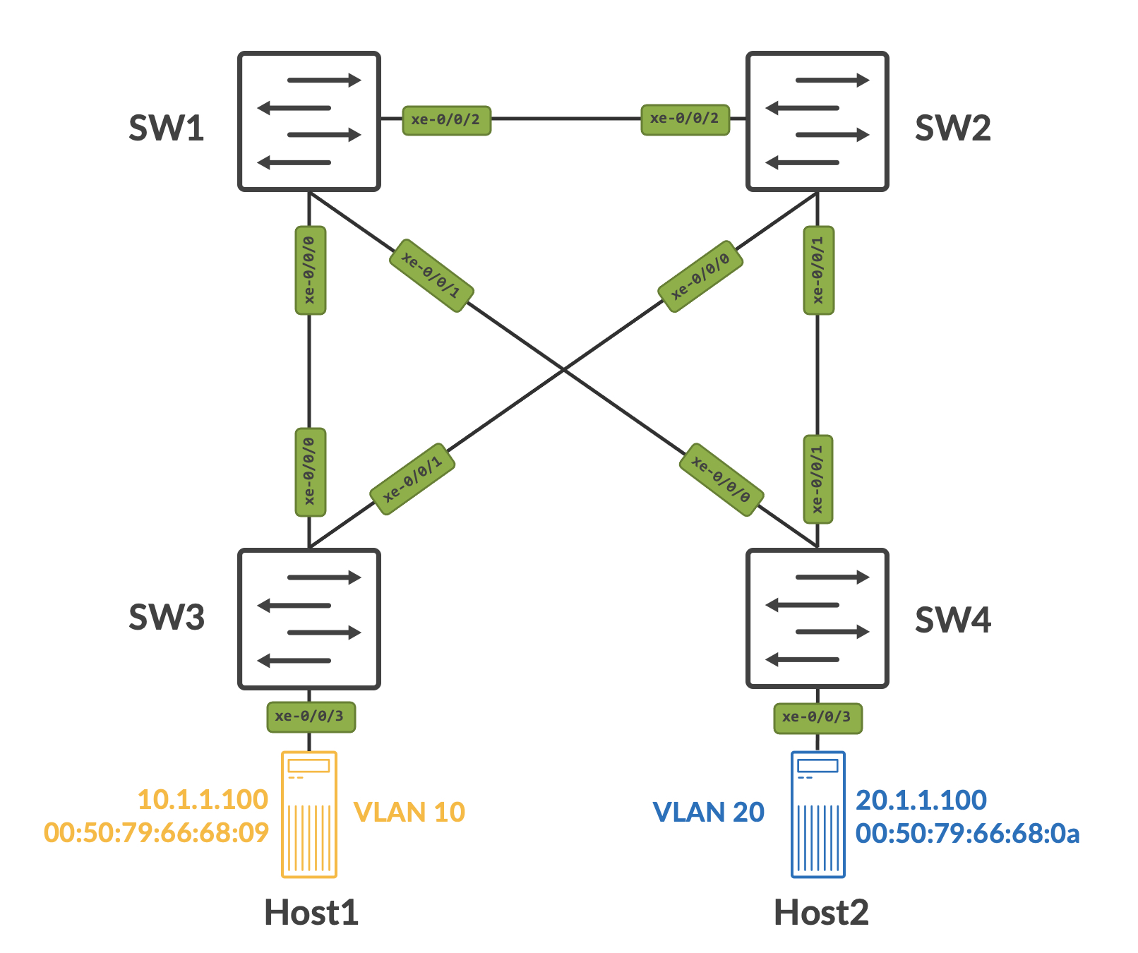
To that end, here’s the topology that we’ll be using for this post. The devices in use are Juniper Networks vQFXs.
Navigating the CLI
Factory default settings
The first, most natural thing, is to learn how to navigate the CLI itself. The Junos OS is a beast of it’s own - at first glance, it seems far more complex than your typical run-of-the-mill Cisco style CLI. You need to give it some time - the kind of quality of life features the Junos OS has is AMAZING.
When you first boot up a factory default Juniper switch (virtual, or hardware), you’ll see something like this:
Amnesiac (ttyd0)

login:
‘Amnesiac’ essentially means the switch is in factory default state. At this point, you can login with ‘root’ and no password.
Amnesiac (ttyd0)

login: root

--- JUNOS 21.4R1.12 built 2021-12-17 14:37:27 UTC

root@:RE:0%
CLI modes
In general, you can be in one of three places in the OS - the shell, operational mode or configuration mode. A non-root user will land in operational mode when logging in.
Moving from the shell to operational mode can be done using the ‘cli’ command, and moving from operational mode to configuration mode can be done using the ‘configure’ command.
// shell

root@SW1:RE:0%

// moving from shell to operational mode

root@:RE:0% cli
{master:0}

// moving from operational mode to configuration mode

root> configure
Entering configuration mode

{master:0}[edit]
Basic configuration and syntax
Junos OS configuration is hierarchical. Notice the ‘edit’ keyword, in brackets, when you entered configuration mode above. This signifies that you are in the edit mode, which is the top most configuration hierarchy. From here, you can start configuring things in two ways:
- You can use set commands directly from the edit mode.
- You can go further down the hierarchy by using additional ‘edit’ commands and then use ‘set’ commands.
To demonstrate this, let’s set a root password for the device, and change the hostname.
Using set commands, we can do this as follows:
{master:0}[edit]
root# set system host-name SW1

{master:0}[edit]
root# set system root-authentication plain-text-password
New password:
Retype new password:

{master:0}[edit]
Using edit commands to go down the hierarchy, we can do the following:
{master:0}[edit]
root# edit system

{master:0}[edit system]
root# set host-name SW1
Notice how the OS tells you exactly where you are in the hierarchy. The ‘edit’ changed to ‘edit system’ because you went to the system level hierarchy. From here, you can issue system level set commands.
To set the root password, we can do the following:
{master:0}[edit system]
root# set root-authentication plain-text-password
New password:
Retype new password:

{master:0}[edit system]
root#
Saving configuration
Junos OS works with the concept of an active and candidate configuration. The active configuration is what the device booted up with and is actively running/using. A candidate configuration is created as soon as you enter configuration mode by typing ‘configure’ or ‘edit’ while in operational mode.
The candidate configuration is essentially a copy of the active configuration, but any changes you make in configuration mode are made to the candidate configuration and not the active configuration. Let that sink in - this is a big shift to what you were potentially used to with vendors like Cisco, and operating systems like IOS/IOS-XE/NX-OS. Any changes made on these would be applied immediately - the purpose of saving the configuration was just to ensure that when the device boots up again, these changes are a part of the configuration.
In Junos OS, to move the changes from the candidate configuration to active configuration (essentially making the candidate configuration the active), you need to ‘commit’ your changes.
root# commit ?
Possible completions:
  <[Enter]>            Execute this command
  activate             Activate a previously prepared commit
  and-quit             Quit configuration mode if commit succeeds
  at                   Time at which to activate configuration changes
  check                Check correctness of syntax; do not apply changes
  comment              Message to write to commit log
  confirmed            Automatically rollback if not confirmed
  no-synchronize       Don't synchronize commit
  peers-synchronize    Synchronize commit on remote peers
  prepare              Prepare for an upcoming commit activation
  scripts              Push scripts to other RE
  synchronize          Synchronize commit on both routing engines
  |                    Pipe through a command
As you can see, there are multiple options to commit changes. The simplest way is just to type commit, and press enter.
root# commit
configuration check succeeds
commit complete
The OS checks for syntax errors, and if none are found, the changes are committed. There are several other handy ways to commit, some of which I use often:
- commit check - this simply checks the configuration for synatx errors, but does not commit them.
- commit confirmed - have you ever locked yourself out of a device because of a change you made? More often than not? Then ‘commit confirmed’ is for you. This commits the changes, but starts a timer as well (default being 10 minutes) - within this time, the user is expected to ‘commit’ the changes again, thus confirming the commit. If the user does not commit the changes again, then the configuration is automatically rolled back.
- commit comment - very git like. You can comment against every commit.
- commit at - allows for commits to be scheduled.
Change diffs and rolling back
Let’s take SW2, as an example, and make some basic changes.
{master:0}[edit]
root# set system host-name SW2

{master:0}[edit]
root# set system root-authentication plain-text-password
New password:
Retype new password:
It is very easy to see what changes are pending to be committed using the ‘compare’ option. All of this is returned in diff style.
root# show | compare
[edit system]
+  host-name SW2;
+  root-authentication {
+      encrypted-password "$6$im9YvqX2$DdZmTiWqRf2O7HAgjFW9ptFsRAT9KXRELcycjG30BkYFMavce7hqwaiz2HznSHVB4FnJStyVdaMD26P1/8WeL1"; ## SECRET-DATA
+  }

{master:0}[edit]
root#
Remember, these changes are not yet commited - this is simply showing us what was added to the candidate configuration, and what isn’t present in the active configuration.
The ‘commit confirmed’ option sheds light into an AMAZING feature on the OS - rollback. Let’s commit our changes first.
root# commit
configuration check succeeds
commit complete

{master:0}[edit]
root@SW2#
Junos OS has a rolling file structure for ‘rollback’ files, with upto 49 rollback files being stored (0 through 49 with 0 being the active configuration itself). The first three commits are stored under /config and anything after that is stored under /var/db/config.
You can also see the full configuration of a rollback file using ‘show system rollback ’. Put together the ‘compare’ option from before, and you have a very powerful tool - you can view changes compared to an earlier version of the configuration, and combined with the rollback feature, you can roll back to it.
So, let’s say I didn’t like the changes I made, and even though I have commited it, I want to go back to my earlier configuration. I can first check what the difference is between my current/active configuration and the rollback I want to go to. Remember, rollback 0 is my active configuration, so there should be no difference between the two.
root@SW2# show | compare rollback 0

{master:0}[edit]
As expected, we see no difference. Let’s try that again with rollback 1 now:
root@SW2# show | compare rollback 1
[edit system]
+  host-name SW2;
+  root-authentication {
+      encrypted-password "$6$im9YvqX2$DdZmTiWqRf2O7HAgjFW9ptFsRAT9KXRELcycjG30BkYFMavce7hqwaiz2HznSHVB4FnJStyVdaMD26P1/8WeL1"; ## SECRET-DATA
+  }
-  commit {
-      factory-settings {
-          reset-virtual-chassis-configuration;
-          reset-chassis-lcd-menu;
-      }
-  }
This is comparing the active and the rollback configuration - the ‘+’ indicates what is present in the active configuration, while the ‘-’ indicates what is in the rollback configuration. When you rollback, the changes are not commited - just like before, they are simply a part of the candidate configuration.
This can be confirmed by doing a compare again, after rolling back:
root@SW2# rollback 1
load complete

{master:0}[edit]
root@SW2# show | compare
[edit system]
-  host-name SW2;
-  root-authentication {
-      encrypted-password "$6$im9YvqX2$DdZmTiWqRf2O7HAgjFW9ptFsRAT9KXRELcycjG30BkYFMavce7hqwaiz2HznSHVB4FnJStyVdaMD26P1/8WeL1"; ## SECRET-DATA
-  }
+  commit {
+      factory-settings {
+          reset-virtual-chassis-configuration;
+          reset-chassis-lcd-menu;
+      }
+  }
This tells us that when we commit these changes, the ‘-’ statements will be removed, and the ‘+’ statements will be added.
Basic Bridging
For bridging, we’ll walk through the creation of VLANs, implement and verify STP, and finally configure SW1 for inter-VLAN routing using L3 interfaces for our VLANs.
Craeting VLANs
VLAN creation is very straightfoward -
{master:0}[edit]
root@SW1# set vlans VLAN10 vlan-id 10

{master:0}[edit]
root@SW1# set vlans VLAN20 vlan-id 20
Once commited, you can see the VLANs via ‘show vlans’:
root@SW1# show vlans
VLAN10 {
    vlan-id 10;
}
VLAN20 {
    vlan-id 20;
}
default {
    vlan-id 1;
}
Creating access and trunk interfaces
On the Junos OS, interfaces function based on physical properties and logical properties. MTU is an example of a physical property. Logical properties fall under something called as a ‘unit’ - a unit can be thought of as a sub-interface (if you’re from the Cisco world). However, having said that, all interfaces will have a unit (even switchports) - the functionality is similar to a sub-interface only when a VLAN tag is associated to it.
The general schema for an interface:
interfaces {
	interface-name {
	    physical-properties;
	    [...]
	    unit <> {
	    logical-properties;
	    [...]
	    }
	}
}
‘family’ is a logical property and this determines the kind of interface you’re configuring. The various family options on the vQFX are:
root@SW1# set interfaces xe-0/0/0 unit 0 family ?
Possible completions:
> ccc                  Circuit cross-connect parameters
> ethernet-switching   Ethernet switching parameters
> inet                 IPv4 parameters
> inet6                IPv6 protocol parameters
> iso                  OSI ISO protocol parameters
> mpls                 MPLS protocol parameters
> vpls                 Virtual private LAN service parameters
For switchports, the family is ‘ethernet-switching’. This family is mutually exclusive to other families like inet or inet6, which means that it cannot be configured alongside any of these other families.
Let’s configure ports xe-0/0/0 and xe-0/0/1 on SW1 to be a trunk interface now:
{master:0}[edit]
root@SW1# set interfaces xe-0/0/0 unit 0 family ethernet-switching interface-mode trunk vlan members [VLAN10 VLAN20]

{master:0}[edit]
root@SW1# set interfaces xe-0/0/1 unit 0 family ethernet-switching interface-mode trunk vlan members [VLAN10 VLAN20]
Remember to delete any other families (which may be configured by default) first. For example, if I have family inet already configured for the interface, and I try to commit family ethernet-switching to the same interface, I get the following error:
root@SW1# set interfaces xe-0/0/4 unit 0 family ethernet-switching

{master:0}[edit]
root@SW1# commit
[edit interfaces xe-0/0/0 unit 0 family]
  'ethernet-switching'
    Family ethernet-switching and rest of the families are mutually exclusive
error: commit failed: (statements constraint check failed)
Before we move on, let’s also configure our host facing interfaces (xe-0/0/3) to be access interfaces in VLAN 10 and 20 respectively.
{master:0}[edit]
root@SW3# set interfaces xe-0/0/3 unit 0 family ethernet-switching interface-mode access vlan members VLAN10

{master:0}[edit]
root@SW4# set interfaces xe-0/0/3 unit 0 family ethernet-switching interface-mode access vlan members VLAN20
Implementing and verifying STP
Assuming all relevant interfaces were configured in the same way on other switches, let’s jump to everyone’s favorite protocol, shall we?
Junos OS offers three flavors of spanning-tree that can be enabled:
- RSTP - this is 802.1w and creates one instance of STP with RSTP mechanisms and enhancements.
- VSTP - this creates one instance of STP for every VLAN, similar to PVST+ on the Cisco side.
- MSTP - this allows you to create your own VLAN to STP instance mappings.
To keep things simple, we’ll enable RSTP across the network now. This is done on a per-interface basis, like so:
{master:0}[edit]
root@SW1# set protocols rstp interface xe-0/0/0

{master:0}[edit]
root@SW1# set protocols rstp interface xe-0/0/1

{master:0}[edit]
root@SW1# set protocols rstp interface xe-0/0/2
We also want to set SW1 as the root bridge for the network, and SW2 as a secondary root bridge. We’ll adjust the bridge priority to influence the election (remember, the default priority is 32768):
{master:0}[edit]
root@SW1# set protocols rstp bridge-priority 4096

{master:0}[edit]
root@SW2# set protocols rstp bridge-priority 8192
Once these changes are commited, we can verify STP state. First, let’s confirm that SW1 is the root bridge. This can be done by looking at the bridge data, and making sure that the bridge ID is the same as the root ID on SW1:
root@SW1> show spanning-tree bridge
STP bridge parameters
Routing instance name               : GLOBAL
Context ID                          : 0
Enabled protocol                    : RSTP
  Root ID                           : 4096.02:05:86:71:c1:02
  Hello time                        : 2 seconds
  Maximum age                       : 20 seconds
  Forward delay                     : 15 seconds
  Message age                       : 0
  Number of topology changes        : 5
  Time since last topology change   : 13227 seconds
  Local parameters
    Bridge ID                       : 4096.02:05:86:71:c1:02
    Extended system ID              : 0
Since SW1 is the root bridge, all participating interfaces should ideally be designated forwarding (barring any exceptions). Interface state can be confirmed using ‘show spanning-tree interface’:
root@SW1> show spanning-tree interface

Spanning tree interface parameters for instance 0

Interface                  Port ID    Designated         Designated         Port    State  Role
                                       port ID           bridge ID          Cost
xe-0/0/0                   128:490      128:490   4096.02058671c102         2000    FWD    DESG
xe-0/0/1                   128:491      128:491   4096.02058671c102         2000    FWD    DESG
xe-0/0/2                   128:492      128:492   4096.02058671c102         2000    FWD    DESG
Let’s look at SW2 now to verify what it sees:
root@SW2> show spanning-tree bridge
STP bridge parameters
Routing instance name               : GLOBAL
Context ID                          : 0
Enabled protocol                    : RSTP
  Root ID                           : 4096.02:05:86:71:c1:02
  Root cost                         : 2000
  Root port                         : xe-0/0/2
  Hello time                        : 2 seconds
  Maximum age                       : 20 seconds
  Forward delay                     : 15 seconds
  Message age                       : 1
  Number of topology changes        : 4
  Time since last topology change   : 13336 seconds
  Local parameters
    Bridge ID                       : 8192.02:05:86:71:39:02
    Extended system ID              : 0
The bridge ID is not the same as the root ID, which implies that SW2 is not the root bridge for this STP instance and the root bridge is the switch with a bridge ID of 4096.02:05:86:71:c1:02. All non-root bridges must have a root port, which is the shortest path to the root - for SW2, this is xe-0/0/2, as seen below:
root@SW2> show spanning-tree interface

Spanning tree interface parameters for instance 0

Interface                  Port ID    Designated         Designated         Port    State  Role
                                       port ID           bridge ID          Cost
xe-0/0/0                   128:490      128:490   8192.020586713902         2000    FWD    DESG
xe-0/0/1                   128:491      128:491   8192.020586713902         2000    FWD    DESG
xe-0/0/2                   128:492      128:492   4096.02058671c102         2000    FWD    ROOT
This same process can be carried out for each of the switches in our network.
Creating L3 interfaces for VLANs and inter-VLAN routing
Creating SVIs or L3 interfaces for corresponding VLANs is a little different from what you’d typically be used to, if you’re coming from the Cisco. For example, in Cisco’s IOS/IOS-XE/NX-OS, you can create the L3 interface as follows:
interface vlan x
    ip address ...
In Junos OS, we use irb interface (on the QFX platform) and vlan interface (on the EX platform) to do the same. This is not enough though - you need to map these L3 interfaces to the L2 VLAN itself.
Let’s create L3 interfaces for both VLAN 10 and VLAN 20 now, on SW1:
{master:0}[edit]
root@SW1# set interfaces irb unit 10 family inet address 10.1.1.1/24

{master:0}[edit]
root@SW1# set interfaces irb unit 20 family inet address 20.1.1.1/24
These are created with a unit, and a family, like any other interface. A good practice is to match the unit to the VLAN number itself (easy to remember it that way) and since we needed an IPv4 interface, we used the inet family here.
We need to map these to the L2 VLAN:
{master:0}[edit]
root@SW1# set vlans VLAN10 l3-interface irb.10

{master:0}[edit]
root@SW1# set vlans VLAN20 l3-interface irb.20
These are now up and running:
{master:0}
root@SW1> show interfaces irb.10
  Logical interface irb.10 (Index 558) (SNMP ifIndex 550)
    Flags: Up SNMP-Traps 0x4004000 Encapsulation: ENET2
    Bandwidth: 1Gbps
    Routing Instance: default-switch Bridging Domain: VLAN10
    Input packets : 14
    Output packets: 325
    Protocol inet, MTU: 1500
    Max nh cache: 75000, New hold nh limit: 75000, Curr nh cnt: 1, Curr new hold cnt: 0, NH drop cnt: 0
      Flags: Sendbcast-pkt-to-re
      Addresses, Flags: Is-Preferred Is-Primary
        Destination: 10.1.1/24, Local: 10.1.1.1, Broadcast: 10.1.1.255

{master:0}
root@SW1> show interfaces irb.20
  Logical interface irb.20 (Index 567) (SNMP ifIndex 551)
    Flags: Up SNMP-Traps 0x4000 Encapsulation: ENET2
    Bandwidth: 1Gbps
    Routing Instance: default-switch Bridging Domain: VLAN20
    Input packets : 14
    Output packets: 264
    Protocol inet, MTU: 1500
    Max nh cache: 75000, New hold nh limit: 75000, Curr nh cnt: 1, Curr new hold cnt: 0, NH drop cnt: 0
      Flags: Sendbcast-pkt-to-re
      Addresses, Flags: Is-Preferred Is-Primary
        Destination: 20.1.1/24, Local: 20.1.1.1, Broadcast: 20.1.1.255
Host1 is configured to have an IP address of 10.1.1.100/4 and Host2 is configured to have an IP address of 20.1.1.100/24, with each of them pointing to the respective L3 VLAN interface on SW1 as their default gateways.
As a final check, let’s confirm reachability. Host1 and Host2 can both ping their gateways, as well as each other.
Host1> ping 10.1.1.1

84 bytes from 10.1.1.1 icmp_seq=1 ttl=64 time=302.328 ms
84 bytes from 10.1.1.1 icmp_seq=2 ttl=64 time=113.679 ms
84 bytes from 10.1.1.1 icmp_seq=3 ttl=64 time=113.723 ms
84 bytes from 10.1.1.1 icmp_seq=4 ttl=64 time=117.448 ms
84 bytes from 10.1.1.1 icmp_seq=5 ttl=64 time=147.437 ms

Host2> ping 20.1.1.1

84 bytes from 20.1.1.1 icmp_seq=1 ttl=64 time=213.357 ms
84 bytes from 20.1.1.1 icmp_seq=2 ttl=64 time=114.515 ms
84 bytes from 20.1.1.1 icmp_seq=3 ttl=64 time=155.711 ms
84 bytes from 20.1.1.1 icmp_seq=4 ttl=64 time=119.110 ms
84 bytes from 20.1.1.1 icmp_seq=5 ttl=64 time=121.898 ms

Host1> ping 20.1.1.100

84 bytes from 20.1.1.100 icmp_seq=1 ttl=63 time=129.036 ms
84 bytes from 20.1.1.100 icmp_seq=2 ttl=63 time=140.484 ms
84 bytes from 20.1.1.100 icmp_seq=3 ttl=63 time=208.669 ms
84 bytes from 20.1.1.100 icmp_seq=4 ttl=63 time=121.458 ms
84 bytes from 20.1.1.100 icmp_seq=5 ttl=63 time=221.929 ms
Following the packet
When Host1 tries to ping Host2, it knows that Host2 is in a different subnet and ARPs for its own default gateway. This ARP is flooded in VLAN 10, and is only stopped from looping around because STP blocked redundant L2 paths. SW1 should get this as well.
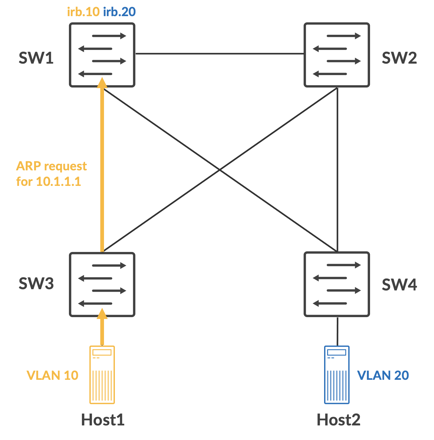
A packet capture on SW1 shows this ARP packet. Also notice that the packet is coming in with a 802.1q tag, with a VLAN ID of 10:
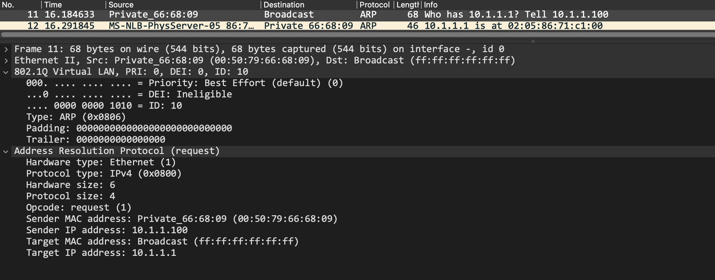
SW1 will respond with an ARP response and Host1 can build its ARP cache using this. Now, it constructs the ICMP request packet and sends it out to SW3.
SW3 will do a MAC address table lookup for the destination MAC address. This tells it to forward the packet out interface xe-0/0/0:
root@SW3> show ethernet-switching table 02:05:86:71:c1:00 vlan-id 10

MAC flags (S - static MAC, D - dynamic MAC, L - locally learned, P - Persistent static, C - Control MAC
           SE - statistics enabled, NM - non configured MAC, R - remote PE MAC, O - ovsdb MAC)


Ethernet switching table : 3 entries, 3 learned
Routing instance : default-switch
    Vlan                MAC                 MAC         Age    Logical                NH        RTR
    name                address             flags              interface              Index     ID
    VLAN10              02:05:86:71:c1:00   D             -   xe-0/0/0.0             0         0
The packet is now sent to SW1. SW1 owns this MAC address, so it does a route lookup now for the destination IP address:
root@SW1> show route table inet.0 20.1.1.100

inet.0: 6 destinations, 6 routes (6 active, 0 holddown, 0 hidden)
+ = Active Route, - = Last Active, * = Both

20.1.1.0/24        *[Direct/0] 20:09:17
                    >  via irb.20
It finds that the destination is directly connected to it, which means SW1 can ARP for it now. The ARP process happens again, and once complete, SW1 forwards the packet out the interface over which it was learned. The packet is now routed from irb.10 to irb.20.
root@SW1> show arp hostname 20.1.1.100
MAC Address       Address         Name                      Interface               Flags
00:50:79:66:68:0a 20.1.1.100      20.1.1.100                irb.20 [xe-0/0/1.0]     none
SW4 gets this and again does a MAC address table lookup for the destination MAC address.
{master:0}
root@SW4> show ethernet-switching table 00:50:79:66:68:0a vlan-id 20

MAC flags (S - static MAC, D - dynamic MAC, L - locally learned, P - Persistent static, C - Control MAC
           SE - statistics enabled, NM - non configured MAC, R - remote PE MAC, O - ovsdb MAC)


Ethernet switching table : 2 entries, 2 learned
Routing instance : default-switch
    Vlan                MAC                 MAC         Age    Logical                NH        RTR
    name                address             flags              interface              Index     ID
    VLAN20              00:50:79:66:68:0a   D             -   xe-0/0/3.0             0         0
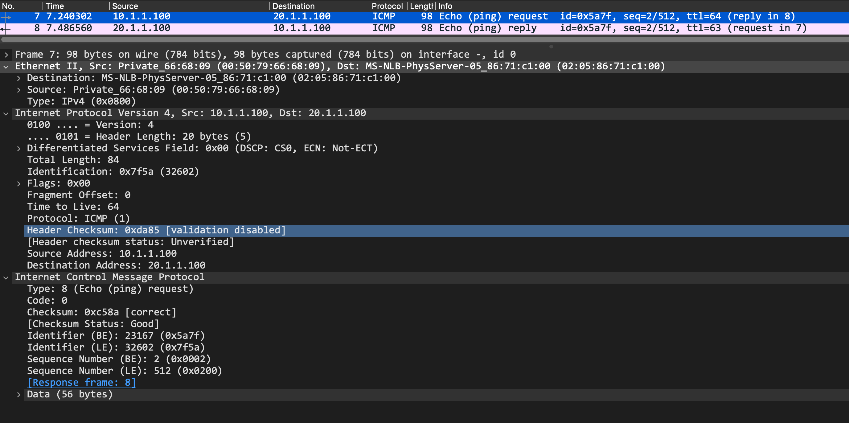
The ICMP request is forwarded out to Host2 and the same process happens in reverse now.
I hope this was informative, and I’d like to thank you for reading!