Cisco SDA part XII - BSR, Auto-RP for the fabric and a catch-22
In this post, we look at why BSR and Auto-RP do not work with a SD-Access fabric.
Introduction and topology
This is the topology that we’ll be working with for this blog post:
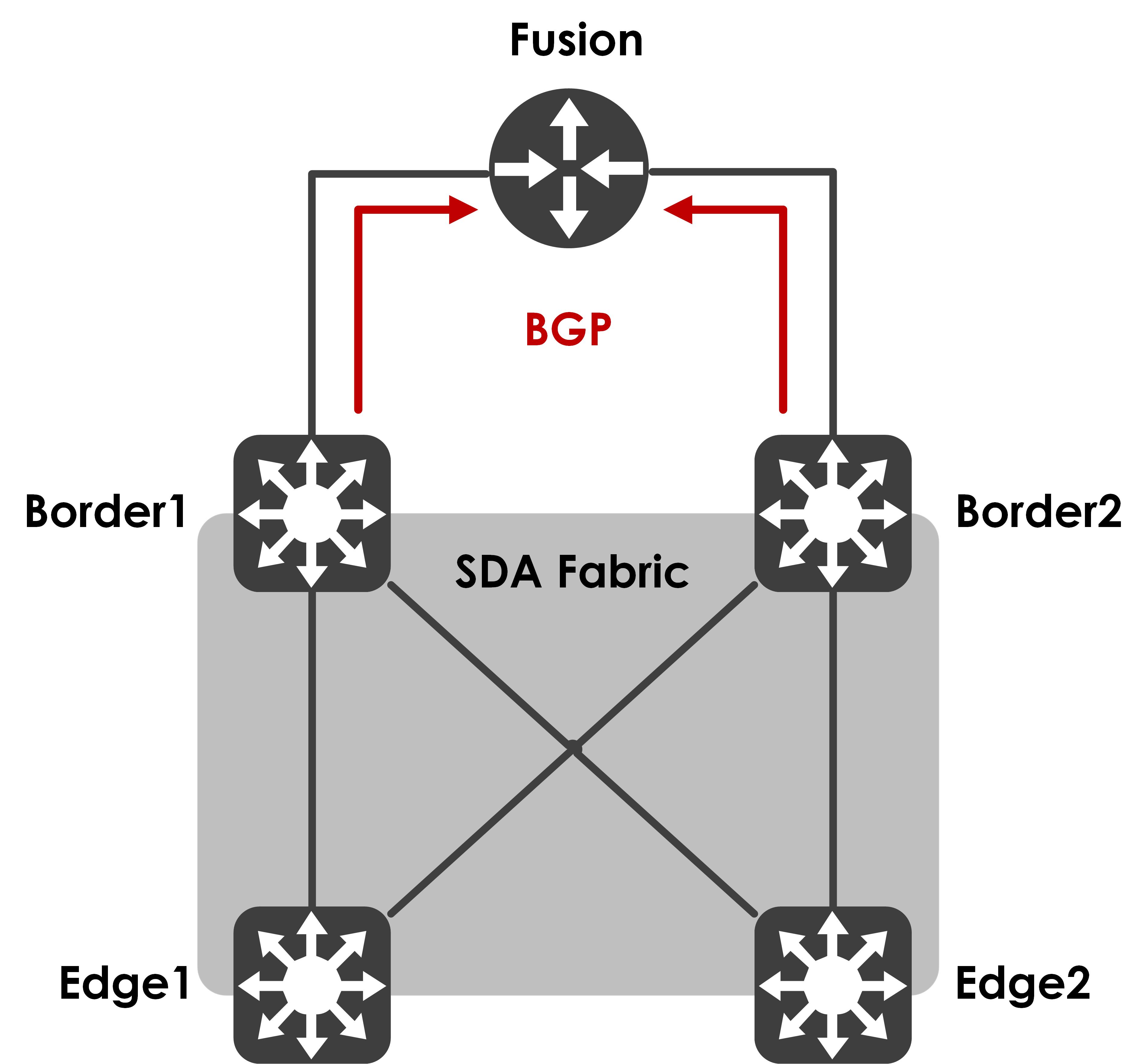
Nothing too fancy - two edges, two co-located control-plane and border devices and a fusion that sits outside of the fabric for inter-VRF (inter-VN) communication.
A lot of customers have their RPs outside of the fabric and want to use one of two protocols that allow for discovery of RP without static assignment - Bootstrap Router (BSR) or Auto-RP (Cisco Proprietary).
The problem with BSR and a SDA fabric
Off the bat, I can tell you that BSR does not (and will not) work with a SDA fabric today - if you closely look at how we form PIM neighbors for the fabric (we don’t, really), it is a static neighbor, enabled by appropriate code based on the RP and the RPF neighbor for it. We’re not really exchanging PIM HELLOs in the overlay and thus, no active neighbor discovery. Don’t believe me? Let’s confirm:
The fusion sees the two borders as active PIM neighbors:
Fusion#show ip pim vrf Corporate neighbor
PIM Neighbor Table
Mode: B - Bidir Capable, DR - Designated Router, N - Default DR Priority,
      P - Proxy Capable, S - State Refresh Capable, G - GenID Capable,
      L - DR Load-balancing Capable
Neighbor          Interface                Uptime/Expires    Ver   DR
Address                                                            Prio/Mode
192.168.1.1       Te0/0/1.3001             03:01:10/00:01:25 v2    1 / S P G
192.168.1.17      Gi0/0/0.3005             03:01:07/00:01:15 v2    1 / S P G
The borders only see the fusion and nothing else:
Border1#show ip pim vrf Corporate neighbor
PIM Neighbor Table
Mode: B - Bidir Capable, DR - Designated Router, N - Default DR Priority,
      P - Proxy Capable, S - State Refresh Capable, G - GenID Capable,
      L - DR Load-balancing Capable
Neighbor          Interface                Uptime/Expires    Ver   DR
Address                                                            Prio/Mode
192.168.1.18      Vlan3005                 03:49:59/00:01:36 v2    1 / DR S P G
The edge (showing just Edge1 as an example here), as expected, sees no neighbor:
Edge1#show ip pim vrf Corporate neighbor
PIM Neighbor Table
Mode: B - Bidir Capable, DR - Designated Router, N - Default DR Priority,
      P - Proxy Capable, S - State Refresh Capable, G - GenID Capable,
      L - DR Load-balancing Capable
Neighbor          Interface                Uptime/Expires    Ver   DR
Address                                                            Prio/Mode
As I said earlier, a neighbor is injected into the PIM neighbor list based on who the RPF neighbor is for the RP. So, let’s test that out - I’ll add a static RP address on Edge1 now.
Edge1(config)#ip pim vrf Corporate rp-address 192.168.250.1
The RPF neighbor for this RP address is:
Edge1#show ip rpf vrf Corporate 192.168.250.1
RPF information for ? (192.168.250.1)
  RPF interface: LISP0.4101
  RPF neighbor: ? (192.168.10.68)
  RPF route/mask: 192.168.250.1/32
  RPF type: unicast ()
  Doing distance-preferred lookups across tables
  RPF topology: ipv4 multicast base
This neighbor now gets inserted into the PIM neighbor list:
Edge1#show ip pim vrf Corporate neighbor
PIM Neighbor Table
Mode: B - Bidir Capable, DR - Designated Router, N - Default DR Priority,
      P - Proxy Capable, S - State Refresh Capable, G - GenID Capable,
      L - DR Load-balancing Capable
Neighbor          Interface                Uptime/Expires    Ver   DR
Address                                                            Prio/Mode
192.168.10.68     LISP0.4101               00:03:53/00:01:55 v2    0 /
This logic, however, breaks BSR functionality with the RP outside of the fabric. Why? Well, BSR uses a flood to all PIM neighbors mechanism (it floods to the multicast destination 224.0.0.13) to forward the candidate RP(s) information - assuming the fusion (in our case) sends this to the borders, which are forming active PIM neighbors with it, the borders, in turn, cannot send this to the edges because the edges never show up as PIM neighbors for it.
Here’s a quote from the BSR RFC to confirm how BSR messages are forwarded:
When a Bootstrap message is forwarded, it is forwarded out of every multicast-capable interface that has PIM neighbors (including the one over which the message was received)
Auto-RP and a catch-22
Auto-RP, however, does work but there’s a catch-22 going on here and I want to make sure everyone understands WHY it works - let’s pull back the curtain, shall we?
Before we get into the fabric specific details, let’s recall how Auto-RP works. Here’s my one minute crash course - Auto-RP uses two multicast groups to distribute RP information, 224.0.1.39 and 224.0.1.40, and includes two new roles for its functionality - candidate RPs and Mapping Agents. The candidate RPs announce their RP address to the mapping agent(s) using 224.0.1.39 and the mapping agent elects one of these as the RP address and announces that to the network using 224.0.1.40.
So, if you want to learn of an RP using Auto-RP, you need to be subscribed to 224.0.1.40, which all Cisco multicast enabled devices do, by default. But, how do you build a multicast tree for a group that you don’t know the RP for? Thus, for the Auto-RP groups, the expectation is to fall back to dense mode to flood these messages. There are several ways to do this, the simplest and easiest is to enable the ‘autorp listener’ feature using the CLI ‘ip pim autorp listener’ or for a specific VRF, using ‘ip pim vrf autorp listener’.
In our topology, I’m going to configure a loopback on the fusion, enable PIM SM on it and put it in the appropriate VRF.
Fusion#show run int loopback1
Building configuration...

Current configuration : 115 bytes
!
interface Loopback1
 vrf forwarding Corporate
 ip address 192.168.250.1 255.255.255.255
 ip pim sparse-mode
end
Next, I’ll advertise this loopback as the candidate RP. The same fusion will also be a mapping agent, just to keep things simple.
Fusion(config)#ip pim vrf Corporate send-rp-announce Loopback1 scope 255 interval 5
Fusion(config)#ip pim vrf Corporate send-rp-discovery scope 255 interval 5
An important point to note - our devices are configured to be autorp listeners by default (not sure from what release for the IOS/IOS-XE platforms). You can confirm this with the following:
Fusion#show run all | in autorp
ip pim autorp
ip pim vrf Corporate autorp
This is only seen with the ‘all’ argument against the running-config, which implies it is a default configuration present on the device. This is important because this allows the device to use PIM dense mode for 224.0.1.39 and 224.0.1.40, which enables the packet to be flooded on all interfaces (dense-mode forwarding rules apply).
The borders get this and are able to derive the RP information from it.
Border1#show ip pim vrf Corporate rp mapping
PIM Group-to-RP Mappings

Group(s) 224.0.0.0/4
  RP 192.168.250.1 (?), v2v1
    Info source: 192.168.1.18 (?), elected via Auto-RP
         Uptime: 12:52:44, expires: 00:00:11
Border2#show ip pim vrf Corporate rp mapping
PIM Group-to-RP Mappings

Group(s) 224.0.0.0/4
  RP 192.168.250.1 (?), v2v1
    Info source: 192.168.1.2 (?), elected via Auto-RP
         Uptime: 09:31:01, expires: 00:00:13
Let’s look at the edge now (taking Edge1 as an example).
Edge1#show ip pim vrf Corporate rp mapping
PIM Group-to-RP Mappings
Edge1 has not received this information. This is because 224.0.1.40 is treated as any other ASM group in the fabric and therein lies the flaw and the catch-22. If you’re using native multicast for the underlay (as an example), this implies that an underlay SSM tree should be built for the packets to be correctly delivered.
How would the underlay SSM tree built if the RP is not known for the group? We use the RP information, find out the RPF neighbor for the RP and build our underlay SSM tree against that neighbor by sending PIM (S,G) joins to it. As you can see, the mroute table for this group on Edge1 has a null incoming interface and the RP is not known.
Edge1#show ip mroute vrf Corporate 224.0.1.40 verbose
IP Multicast Routing Table
Flags: D - Dense, S - Sparse, B - Bidir Group, s - SSM Group, C - Connected,
       L - Local, P - Pruned, R - RP-bit set, F - Register flag,
       T - SPT-bit set, J - Join SPT, M - MSDP created entry, E - Extranet,
       X - Proxy Join Timer Running, A - Candidate for MSDP Advertisement,
       U - URD, I - Received Source Specific Host Report,
       Z - Multicast Tunnel, z - MDT-data group sender,
       Y - Joined MDT-data group, y - Sending to MDT-data group,
       G - Received BGP C-Mroute, g - Sent BGP C-Mroute,
       N - Received BGP Shared-Tree Prune, n - BGP C-Mroute suppressed,
       Q - Received BGP S-A Route, q - Sent BGP S-A Route,
       V - RD & Vector, v - Vector, p - PIM Joins on route,
       x - VxLAN group, c - PFP-SA cache created entry
Outgoing interface flags: H - Hardware switched, A - Assert winner, p - PIM Join
 Timers: Uptime/Expires
 Interface state: Interface, Next-Hop or VCD, State/Mode

(*, 224.0.1.40), 00:00:28/00:02:36, RP 0.0.0.0, flags: DCL
  Incoming interface: Null, RPF nbr 0.0.0.0
  Outgoing interface list:
    Loopback4101, Forward/Sparse, 00:00:28/00:02:36
Thus, if I manually add the RP on Edge1, I should now see Auto-RP packets as well.
Edge1(config)#ip pim vrf Corporate rp-address 192.168.250.1
Now, I see the mroute table built correctly as well:
Edge1#show ip mroute vrf Corporate 224.0.1.40 verbose
IP Multicast Routing Table
Flags: D - Dense, S - Sparse, B - Bidir Group, s - SSM Group, C - Connected,
       L - Local, P - Pruned, R - RP-bit set, F - Register flag,
       T - SPT-bit set, J - Join SPT, M - MSDP created entry, E - Extranet,
       X - Proxy Join Timer Running, A - Candidate for MSDP Advertisement,
       U - URD, I - Received Source Specific Host Report,
       Z - Multicast Tunnel, z - MDT-data group sender,
       Y - Joined MDT-data group, y - Sending to MDT-data group,
       G - Received BGP C-Mroute, g - Sent BGP C-Mroute,
       N - Received BGP Shared-Tree Prune, n - BGP C-Mroute suppressed,
       Q - Received BGP S-A Route, q - Sent BGP S-A Route,
       V - RD & Vector, v - Vector, p - PIM Joins on route,
       x - VxLAN group, c - PFP-SA cache created entry
Outgoing interface flags: H - Hardware switched, A - Assert winner, p - PIM Join
 Timers: Uptime/Expires
 Interface state: Interface, Next-Hop or VCD, State/Mode

(*, 224.0.1.40), 00:02:09/00:02:57, RP 192.168.250.1, flags: SJCL
  Incoming interface: LISP0.4101, RPF nbr 192.168.10.68, LISP: [192.168.10.68, 232.0.1.180]
  Outgoing interface list:
    Loopback4101, Forward/Sparse, 00:02:09/00:02:57

(192.168.1.18, 224.0.1.40), 00:00:02/00:02:57, flags: LJT
  Incoming interface: LISP0.4101, RPF nbr 192.168.10.68, LISP: [192.168.10.68, 232.0.1.180]
  Outgoing interface list:
    Loopback4101, Forward/Sparse, 00:00:02/00:02:57
The RPF neighbor points to Border1 and Edge1 (and Edge2) sends a (S,G) join in the underlay towards Border1, building this SSM tree. On Border1, we see the correct state, allowing for the auto-RP messages to flow to the edges.
Border1#show ip mroute 232.0.1.180 verbose
IP Multicast Routing Table
Flags: D - Dense, S - Sparse, B - Bidir Group, s - SSM Group, C - Connected,
       L - Local, P - Pruned, R - RP-bit set, F - Register flag,
       T - SPT-bit set, J - Join SPT, M - MSDP created entry, E - Extranet,
       X - Proxy Join Timer Running, A - Candidate for MSDP Advertisement,
       U - URD, I - Received Source Specific Host Report,
       Z - Multicast Tunnel, z - MDT-data group sender,
       Y - Joined MDT-data group, y - Sending to MDT-data group,
       G - Received BGP C-Mroute, g - Sent BGP C-Mroute,
       N - Received BGP Shared-Tree Prune, n - BGP C-Mroute suppressed,
       Q - Received BGP S-A Route, q - Sent BGP S-A Route,
       V - RD & Vector, v - Vector, p - PIM Joins on route,
       x - VxLAN group, c - PFP-SA cache created entry,
       * - determined by Assert
Outgoing interface flags: H - Hardware switched, A - Assert winner, p - PIM Join
 Timers: Uptime/Expires
 Interface state: Interface, Next-Hop or VCD, State/Mode

(192.168.10.68, 232.0.1.180), 13:28:09/00:03:08, flags: sTp
  Incoming interface: Null0, RPF nbr 0.0.0.0
  Outgoing interface list:
    TenGigabitEthernet1/1/1, Forward/Sparse, 00:02:32/00:03:06, Pkts:0, p
    TenGigabitEthernet1/1/2, Forward/Sparse, 13:15:29/00:03:08, Pkts:0, p
A packet capture confirms that the Auto-RP messages are now flowing via the overlay, encapsulated with a VXLAN header:
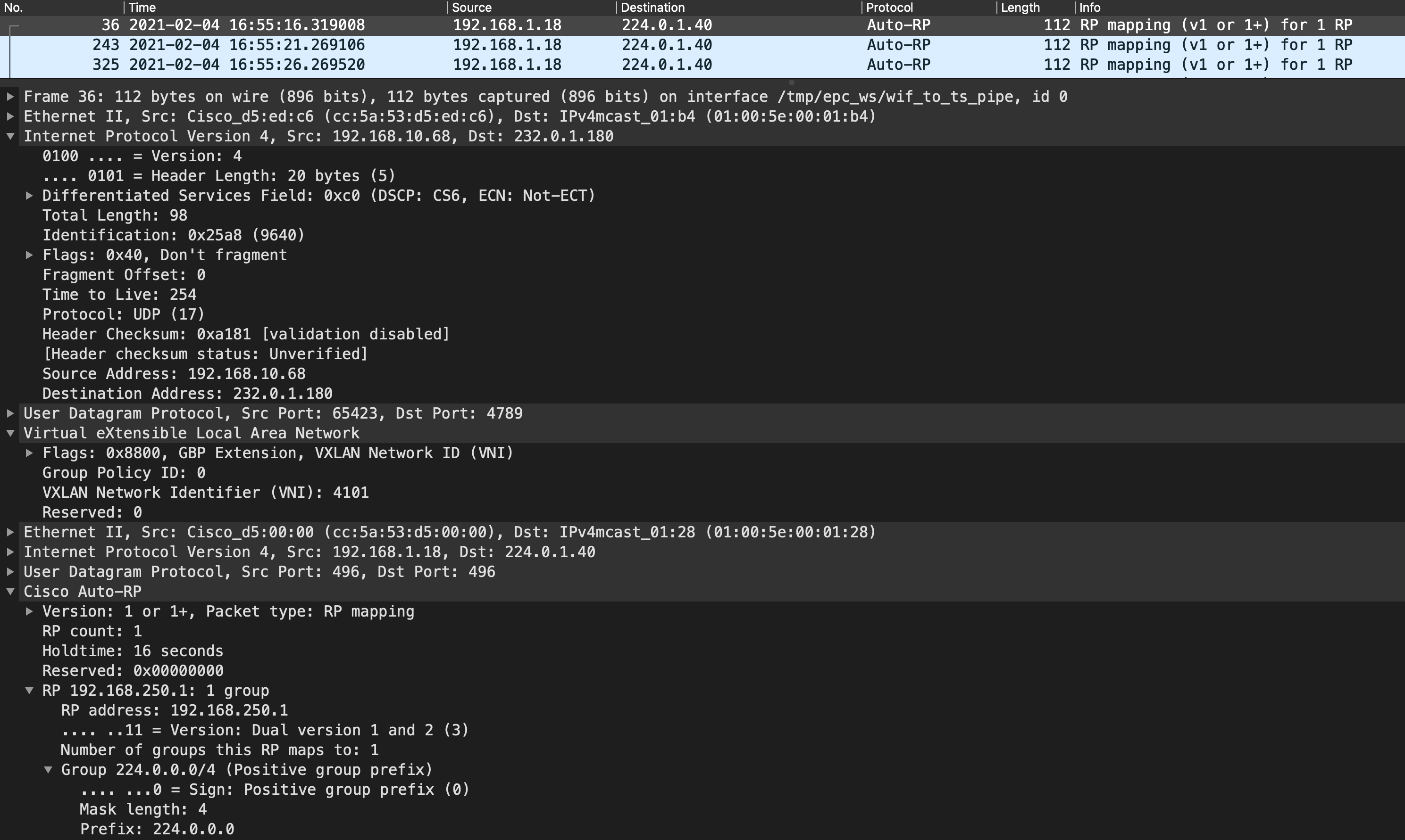
There you have it - Auto-RP in SDA isn’t really going to work unless you statically configure the RP as well (which defeats the purpose of Auto-RP, doesn’t it?). I do feel that the implementation for BSR and Auto-RP groups should be changed - 224.0.1.13, 224.0.1.39 and 224.0.1.40 should be a “special” case and we should use L2 Flooding to flood these packets in the underlay ASM group, pre-built for L2 Flooding (which will get these messages to all edges).
I hope this was informative and as always, I’d like to thank you for reading, if you’ve come this far.